7 summary of changes – Rice Lake 920i USB Installation Manual V5.05 User Manual
Page 12
6
920i Installation Manual
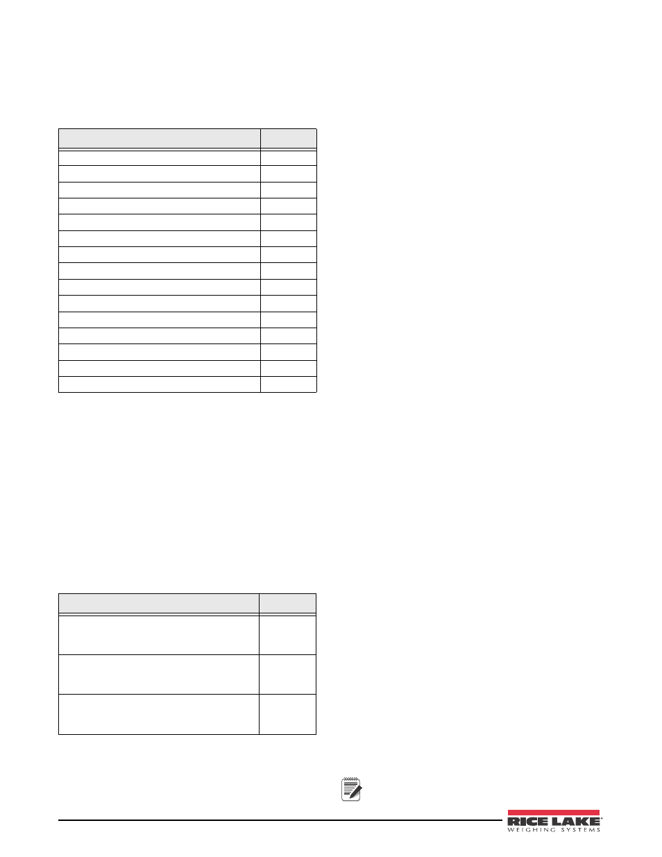
Option Cards
Table 1-5 lists the available 920i option cards. Any of
the listed option cards can be installed in Slot 2 of the
CPU board or in any available slot of an attached
expansion board.
Table 1-5. Part Numbers for 920i Option Cards
Option Card
PN
Single-channel A/D card
68532
Dual-channel A/D card
68533
Single-channel analog output card
67602
Dual-channel analog output card
103138
Dual serial port expansion card
67604
24-channel digital I/O expansion card
67601
1MB NV RAM memory expansion card
67600
Pulse input card
67603
Ethernet communications card
71986
EtherNet/IP interface card
87803
DeviceNet interface card
68541
Allen-Bradley Remote I/O interface card
68539
Profibus DP interface card
68540
ControlNet interface card
103136
Analog input card with thermocouple input
87697
Expansion Boards
Table 1-6 lists the expansion boards available for the
panel mount and wall mount enclosures. The panel
mount enclosure can accommodate a single 2-card
expansion board; the wall mount enclosure supports
either a 2-card or a 6-card expansion board. Any of the
available option cards can be installed in any available
expansion board slot.
A second two- or six-card expansion board can also be
connected to the 920i, providing up to 14 option card
slots. Consult factory for details. See Section 2.5 on
page 15 for detailed information about slot and serial
port assignments for expanded system configurations.
Table 1-6. Part Numbers for 920i Expansion Boards
Expansion Board
PN
Two-card expansion board for panel mount
enclosure, slots 3–4. Includes 2-inch, 34-pin
ribbon cable and power supply cable.
71743
Two-card expansion board for wall mount
enclosure, slots 3–4. Includes 24-inch, 34-pin
ribbon cable and power supply cable.
69782
Six-card expansion board for wall mount
enclosure, slots 3–8. Includes 16-inch, 34-pin
ribbon cable and power supply cable.
69783
Relay Options
8-, 16-, and 24-channel relay racks are available for all
920i systems. Relays can be installed internally in the
wall mount enclosure; all other models require an
external enclosure for the relays. Consult factory for
details.
DC Power Supplies
Two DC power supplies are available for mobile 920i
applications:
PN 97474, 9–36 VDC supply
PN 99480, 10–60 VDC supply
Consult factory for more information.
Outdoor Display
An optional display, PN 100759, is available for
applications requiring use of the 920i in bright, sunlit
environments. Consult factory for details.
1.7
Summary of Changes
Version 5.05
• Several bug fixes
Version 5.02
Added USB support.
• Allow a print to host PC.
• Added SCx.ESNAP for a snapshot using iQUBE
2
.
• Changed InitDatRecording to return an unrounded
value.
• Added StartWeightCollection and
StopWeightCollection APIs.
• Added support for multiple port 4Key streaming.
Version 5.00
• Added USB support.
Version 4.01
• HWSUPPORT returns part number of the CPU
board (see Section 10.1.3 on page 95).
• The new CPU board (PN 109549) was designed to
take advantage of newer technology and eliminate
any parts that are at end-of-life stage.
• There is no SDRAM module on the back side as the
memory is now on the main board.
• Added two additional DIO points, 5 and 6.
• The new boot monitor V2.03 has mapping for the
new memory.
• The new board requires minimum version 3.14 or
newer. Version 3.14 supports
iQUBE
while 4.xx
supports iQUBE
2
.
Version 4.0
• Added support for iQUBE
2
and removed support
for
iQUBE
.
Note
Version 4.0 requires Rev E CPU board or
newer.