4 serial scale interface, 5 local/remote operation – Rice Lake 920i USB Installation Manual V5.05 User Manual
Page 123
Appendix
117
11.4
Serial Scale Interface
Serial ports 3 through 32 can be configured for serial
scale input. The serial scale function allows other scale
indicators to send gross, net, or tare weight data to the
920i. Once a serial port has been configured to accept
scale data, the data format can be customized to match
the data stream sent by that indicator.
To configure a serial scale, do the following:
1. Under the SERIAL menu, set the INPUT
parameter for the selected port to SCALE
( l e g a l - f o r- t r a d e s e r i a l s c a l e ) o r I N D U S T
(industrial serial scale).
2. Return to the SCALES menu. Under CONFIG,
drop down and select the serial port. If the serial
scale is not shown, press the
Change Type
softkey
to select available serial scales, then use the
navigational keys to select the serial scale. Press
Add
to move the scale to the righthand column,
the press
Done
.
3. Under the SERIAL menu, return to the selected
p o r t a n d s e t t h e f o r m a t u n d e r t h e S F M T
parameter to match the format sent by the serial
scale.
The default serial scale format is:
<2>
where:
<2>
STX character
Polarity
Seven characters of net data with decimal point
Mode
Units
Status
Carriage return
Line feed
NOTE:
Industrial serial scales (INDUST) do not require
the
,
, and
identifiers. However, the units and
number of decimal places must be specified. Units can be
selected from the FORMAT menu; decimal places should
be indicated on the w-spec identifier. For example, a
seven-digit weight requiring two decimal places should be
specified as
rather than
.
See Section 11.6 for more information about stream
formatting and format identifiers.
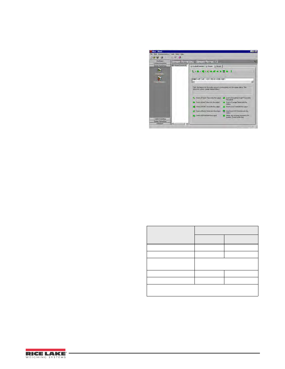
iRev 4 provides several preset scale formats within its
Stream Formatting function. Figure 11-1 shows one of
the iRev 4 stream formatting displays.
Figure 11-1. iRev 4 Stream Formatting Display
11.5
Local/Remote Operation
For truck scale and similar applications, local/remote
support provides function equivalent to that of a
legal-for-trade remote display with keypad. Scale data from
the local indicator is also displayed at the remote unit, and
keypad input from the remote allows transactions to be
initiated from either the local or remote unit.
To configure for local/remote operation, first set up the
local scale (including softkey assignments, truck mode,
and database information, as required). Use the
SERIAL menu, serial commands, or iRev 4 to set the
Local Unit serial parameters shown in Table 11-7.
Configure the remote indicator using the serial
parameters listed for the Remote Unit.
Table 11-7. Local/Remote Configuration Parameters
Serial
Configuration
Parameter
Parameter Value
Local Unit
Remote Unit
EDP.INPUT#p
CMD
DISPLAY
EDP.STREAM#p
DISPLAY
KEYPAD
EDP.BAUD#p
115200 preferred; local and
remote values must match
EDP.ECHO#p
OFF
OFF
EDP.RESPONSE#p
ON
ON
In the listed serial commands, p represents the serial port
number.