In-1 transducer (accessory) – CDI Torque MULTITEST Government User Manual
Page 86
6-8
2000-600-02 Manual Loader
4-in-1 Transducer (Accessory)
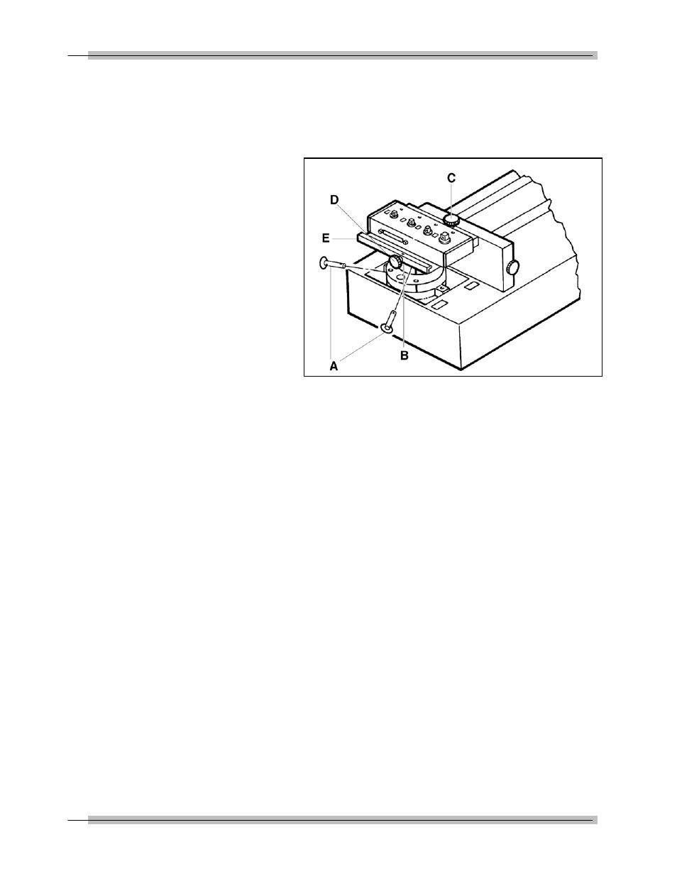
The 4-in-1 transducer is mounted to the loader using the
standoff fixture and bracket assembly as shown in Figure 6-5.
Figure 6-5: 4-in-1 Transducer on 2000-600-02 Manual Loader
A — Quick Release Pins
Four quick release pins must be installed. The first two secure
the standoff fixture to the loader and the second two lock the
adaptor to the transducer bracket.
B — Loader Standoff (under bracket)
The standoff and bracket must be installed into the loader by
lining up the holes of the standoff to the holes of the loader.
C & D — Bracket Knobs
Two knobs on the bracket are used to align the selected
transducer over the loader drive. Tighten the left knob (D) first,
then the top knob (C). The wrench or driver to be tested is then
coupled to the selected transducer using an internal-internal
adaptor.
E — 4-in-1 Adapter Bracket
Holds the 4-in-1 transducer horizontal to the loader.