Multitest indicator, Front panel – CDI Torque MULTITEST Government User Manual
Page 19
2-3
Functional Description and Specifications
MULTITEST Indicator
This section describes the major hardware components of the
MULTITEST Indicator, including:
• Front Panel
• Rear Panel (Input/Output)
• MULTITEST Torque/Force Transducers
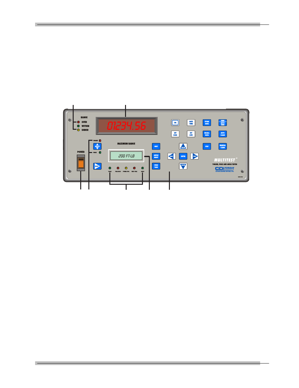
Front Panel
Figure 2-3: 2000-610-02 Front Panel
A — MULTITEST Torque/Force Display
TORQUE or FORCE displays on a bright red alphanumeric
LED, with 0.55" high characters in selected engineering UNITs.
• (+) = Clockwise torque or force
• (-) = Counter clockwise torque or force
B — Range LED Torque or Force Limit Indicators
• Red—OVER (Input exceeds 110% of transducer range)
• Green—WITHIN (Input is within transducer range)
• Yellow—UNDER (Input is below transducer range)
C — Power Switch
• Red—TORQUE
• Green—FORCE
D — Mode Select LEDs
E — MODE Function LEDs
• Green—TRACK
• Red—PEAK HOLD
• Yellow—POWER TOOL
• Red—FIRST PEAK
• Green—ANGLE
B
A
C D
E
F
G