Multitest indicator controls – CDI Torque MULTITEST Government User Manual
Page 33
B
A
C D
E
F
G
3-3
Setup and Programming
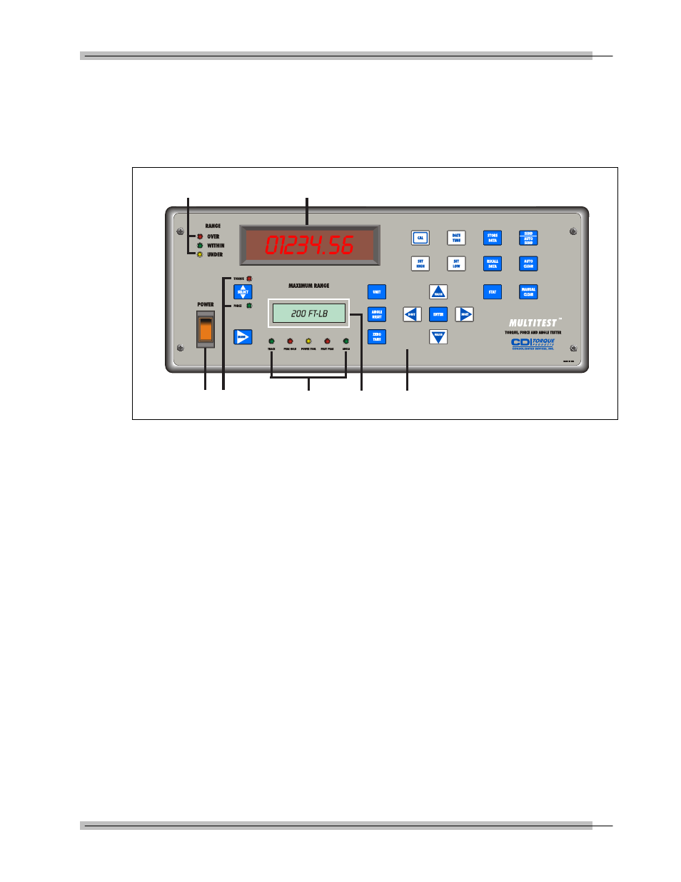
MULTITEST Indicator Controls
Refer to the illustration below when performing the power-up
and programming procedures.
Figure 3-2: Indicator Controls
A – MULTITEST Torque/Force Display
B – Range LED Torque or Force Limit Indicators
C – Power Switch
D – Load Select LEDs
E – MODE Function LEDs
F – Maximum Range Display
G – Front Panel Membrane Function Keys