CDI Torque MULTITEST Government User Manual
Page 24
2-8
Functional Description and Specifications
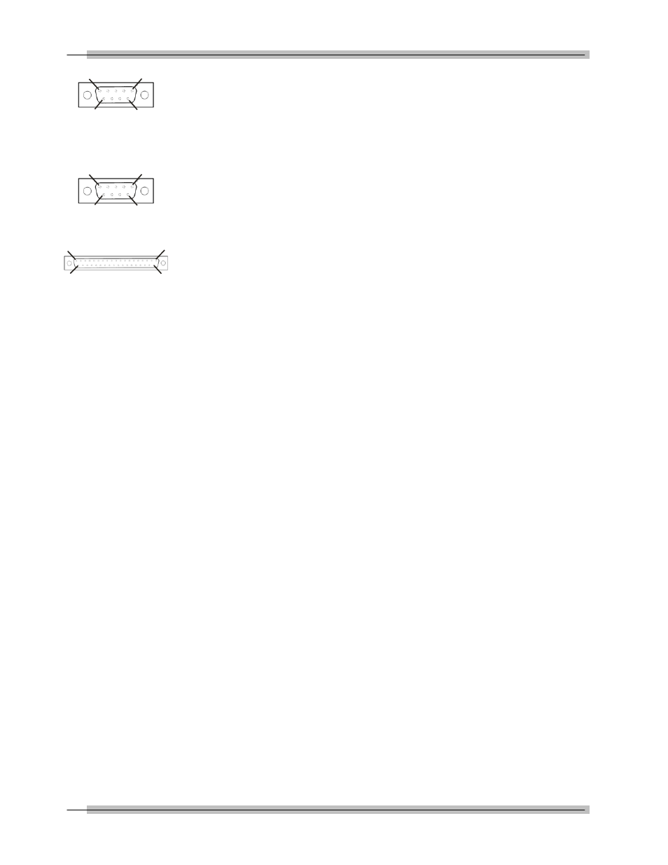
D — PRINTER PORT (DB-9P)
PIN
FUNCTION
2
Receive
3
Transmit
5
Ground
E — OPTIONAL (DB-9P)
PIN
FUNCTION
2
Receive
3
Transmit
5
Ground
F — TRANSDUCER INPUT (DB-37S)
PIN
FUNCTION
1
not used
2
ground
3
smart chip - bit 2
4
smart chip - bit 0
5
single xducer (-) signal
6
single xducer (+) signal
7
ground
8
4-in-1 xducer (-) signal 2
9
4-in-1 xducer (+) signal 2
10
ground
11
4-in-1 xducer (-) signal 4
12
4-in-1 xducer (+) signal 4
13
4-in-1 xducer LED 2
14
4-in-1 xducer LED 4
15
loader relay CW limit
16
rotary encoder signal A
17
rotary encoder signal B
18
ground
19
bridge excitation (+3V)
20
not used
21
smart chip - bit 3
22
smart chip - bit 1
23
ground
24
ground
25
4-in-1 xducer (-) signal 1
26
4-in-1 xducer (+) signal 1
27
ground
28
4-in-1 xducer (-) signal 3
29
4-in-1 xducer (+) signal 3
30
no transducer
31
4-in-1 xducer LED 1
32
4-in-1 xducer LED 3
33
loader relay CCW limit
34
loader relay common
35
Vcc (+5V@100 ma. max)
36
ground
37
bridge excitation (+3V)
G — VOLTAGE SELECT
Switch for selecting either 120VAC or 220VAC, 50-60 Hz.
37
19
1
20
1
5
9
6
1
5
9
6