Display assembly latch, Palmrest assembly – Dell Inspiron 3700 User Manual
Page 121
3. Place the inverter in the cover top.
4. Reinstall the three 3-mm screws that secure the inverter to the top cover.
5. Connect the LCD flex cable to the ZIF connector on the inverter.
Replacing the 12.1-Inch LCD Panel
1. Find the manufacturer
’s name on the back of the LCD panel that is to be installed.
The manufacturer is either Torisan or Sharp.
4. Place the bottom edge of the LCD panel in the bottom of the top cover and elevate the top of the panel with your hand.
5. Carefully connect the LCD flex cable to the connector on the left edge of the LCD panel.
The flex cable must be curled back to connect to the LCD panel (see Figure 16).
Do not force the LCD flex cable into the connector. If you have trouble, check to make sure the LCD flex cable is folded correctly and try
again.
6. Lay the LCD panel in the top cover.
7. Connect the two-wire backlight plug to the connector on the inverter.
When the plug is all the way in the connector, the key slot in the center of the plug should not be visible. If you can see the key slot, the plug is
not in the connector correctly. Pull the plug out, turn the plug over, and reinsert it into the connector.
8. Reinstall the four 5-mm screws to secure the LCD panel to the top cover.
Display Assembly Latch
To remove the display assembly latch, perform the following steps.
NOTICE: To avoid damaging the system board, remove the power cable, the battery, and the second battery (if installed) before you
service the computer.
1. Remove the display assembly bezel.
2. Remove the LCD panel.
Palmrest Assembly
The palmrest assembly consists of the touch pad and the palmrest. To remove the palmrest assembly, perform the following steps.
NOTICE: The reserve battery provides power to the computer
’s RTC and NVRAM when the computer is turned off. Removing the
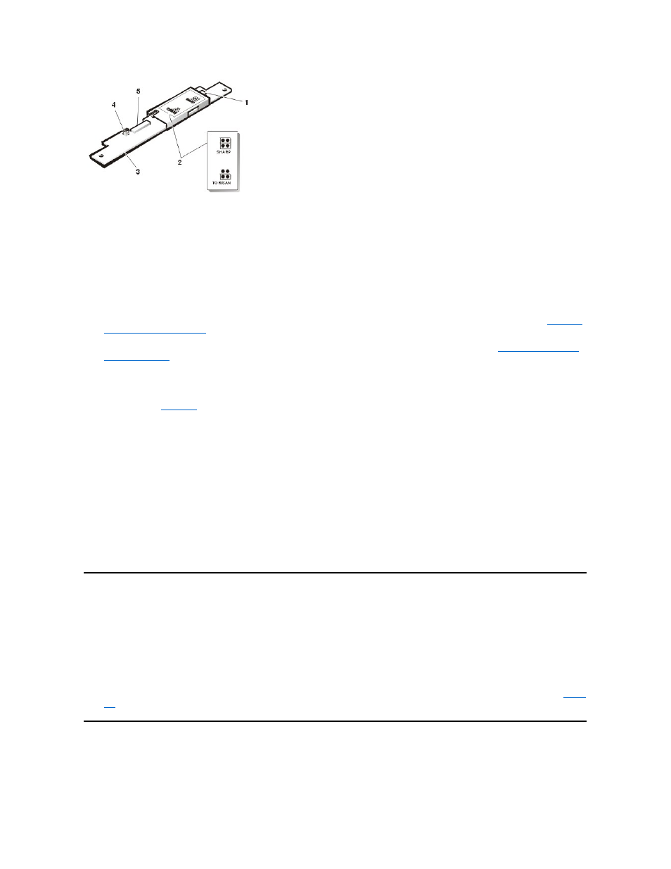
1 Backlight connector
2 Label
3 Inverter
4 Jumpers
5 ZIF connector
NOTICE: The LCD flex cable must be folded correctly before the cable connector can be attached to the connector on
the LCD panel (see