Liquid fertilizer strainer(s), Fertilizer relief valve – Great Plains YP2425F-2470 Operator Manual User Manual
Page 65
Great Plains Manufacturing, Inc.
Adjustments
61
2014-07-14
401-406M
Liquid Fertilizer Strainer(s)
The optional ground drive fertilizer pump systems
include a strainer at each pump. The Type 3 system
relies on strainers at the source, usually on a tank cart.
The strainer(s) are delivered with a mesh screen. You
need to check that each screen is an appropriate size for
the orifice plates you plan to use.
If changing screen sizes, keep in mind the following:
• Generally, select a mesh screen the same or slightly
smaller than the orifice size.
• A substantially smaller mesh (e.g. 100) will reduce
manifold orifice plates plugging so often, but the
strainer screen will have to be cleaned more often.
• A much larger mesh (e.g. 50 or 30) will pass more
material but should only be considered when using
large manifold orifice plates.
• A plugged or partially plugged screen will starve the
pump and will result in a reduced application rate.
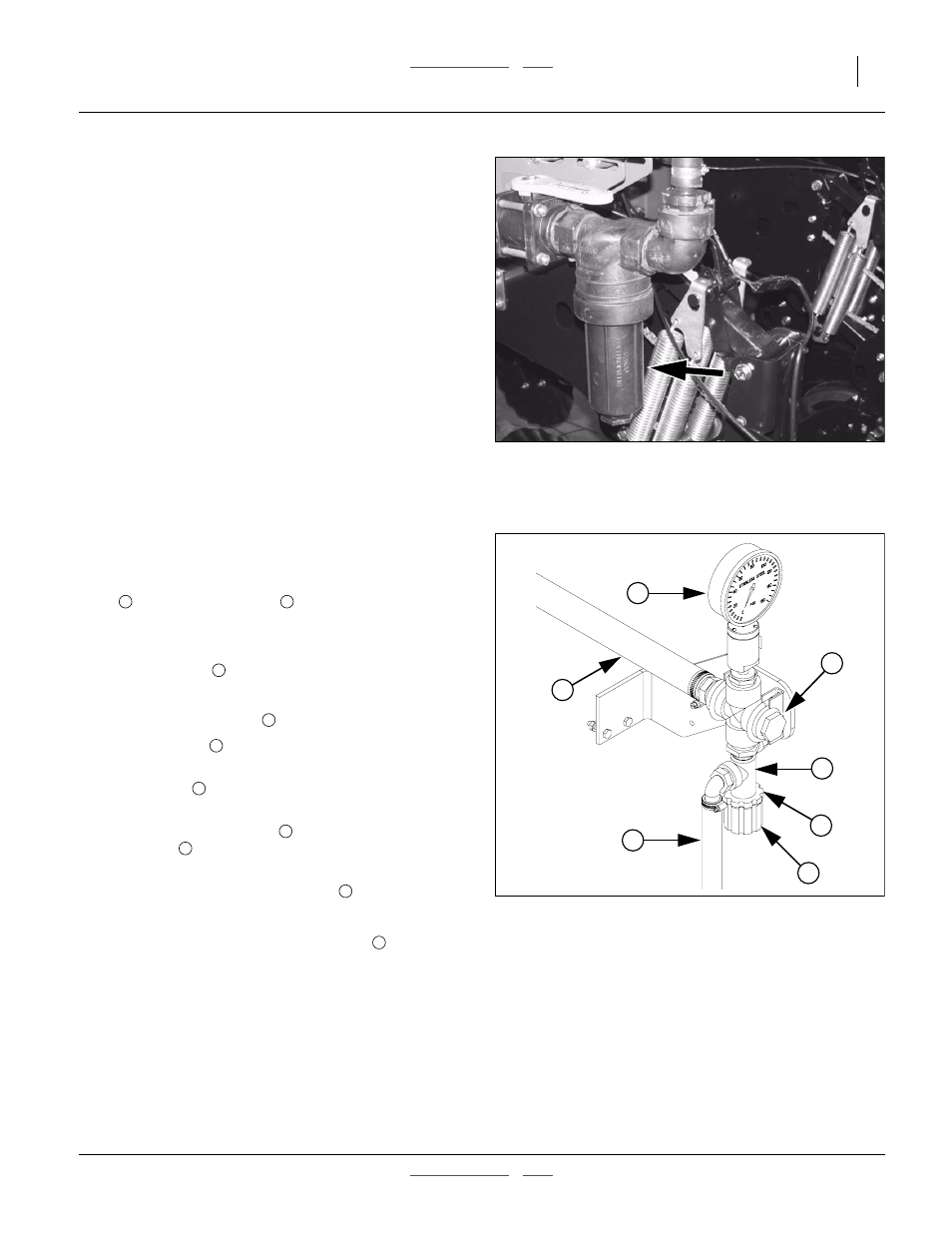
Fertilizer Relief Valve
Refer to Figure 71
When a “Type 2” fertilizer system is installed, a relief
valve
and pressure gauge
are mounted at each
ground drive pump. The relief valve protects the
manifold, lines and fittings from excessive pressure. Any
product that dumps over the relief valve will discharge
from the dump line
in relative safety.
To set relief valve:
1.
Unlock plastic jam nut
from relief valve knob.
2.
Unscrew knob
clockwise (looking down) until it
loses contact with internal spring.
3.
Screw knob
counterclockwise two turns.
Start at this setting.
4.
Observe manifold gauge
and watch for relief valve
dump line
discharge while operating in the field.
5.
If valve is dumping product and gauge reads under
65 psi, stop tractor and turn knob
clockwise
1
⁄
4
turn. Continue operating at normal field speed.
Repeat this step as needed until no product is
discharged from relief valve dump line
.
6.
If the pressure gauge reads above 65 psi, change to
a larger orifice. Go to step 2 and repeat.
Figure 70
Strainer
21965
Figure 71
Fertilizer Relief Valve
25164
1
2
3
4
5
6
7
1
2
5
6
7
7
2
5
7
5