Electric clutch operation, Clutch switch coverage, Row (30in single) – Great Plains YP2425F-2470 Operator Manual User Manual
Page 45: Row (20in single), Row (15in single), Row (30in twin), Electric clutch lock-up, Clutch switch coverage electric clutch lock-up
Great Plains Manufacturing, Inc.
Operating Instructions
41
2014-07-14
401-406M
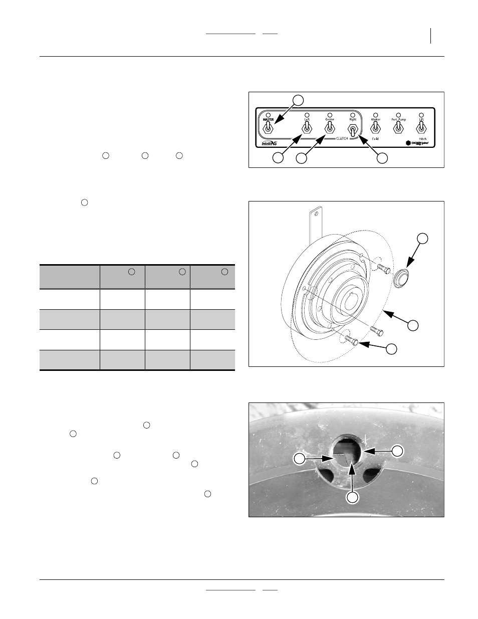
Electric Clutch Operation
A clutch enables or disables groups of row units. The
standard YP24 planter has three clutches in the seed
meter drive system.
The standard clutch system is strictly operator controlled.
Monitor control of sections requires the optional Swath
Command™ system (page 42).
The switches Left
/ Center
/ Right
correspond to
the left wing row units, center section row units and right
wing row units respectively. The data in the table below is
normally preset at the factory for your planter
configuration.
The Master
switch controls all row units, regardless of
drive type. For all switches, “OFF” (down) removes power
from the clutch, disengaging that set of row units. When
any switch (plus Master) is ON, the LED for that switch
illuminates steadily.
Clutch Switch Coverage
Electric Clutch Lock-Up
In case of electric clutch failure, an electric clutch can be
mechanically engaged.
Refer to Figure 40 and Figure 41
1.
Remove the rubber plugs
disc
to allow access to the lock-up holes. Plugs
simply push out away from the clutch side.
2.
Align the cutouts
with the holes
. If you observe
half the hole obstructed by a metal disc
, you are
not at a cutout. If the entire hole is obstructed by a
metal disc
, you are not at a cutout.
3.
Insert the M8-1.25x14mm long metric bolts
When at a cutout, the bolt screws in with minimal
resistance until the bolt head reaches the clutch
face.
4.
Re-install the plugs so they are not lost.
Note: Use only the provided 14 mm length bolts. Longer
bolts will damage the clutch. Shorter bolts may not
effect a lock-up.
Left
Rows
Center
Rows
Right
Rows
24-Row
(30in Single)
1-9
10-15
16-24
36-Row
(20in Single)
1-14
15-22
23-36
47-Row
(15in Single)
1-18
19-29
30-47
48-Row
(30in Twin)
1-18
19-30
31-48
Figure 39
CFM: Clutch Switches
26120
1
2
3
4
2
3
4
Figure 40
Electric Clutch Lockup
29329
5
1
2
1
2
3
4
Figure 41
Clutch Plate Nearly at Cutout
26168
6
4
3
1
6
5