Ultra-cut 400 xt, Caution – Tweco 400 XT Ultra-Cut Plasma Cutting System With Automated Gas Control User Manual
Page 36
ULTRA-CUT 400 XT
3-14
INSTALLATION
Manual 0-5306
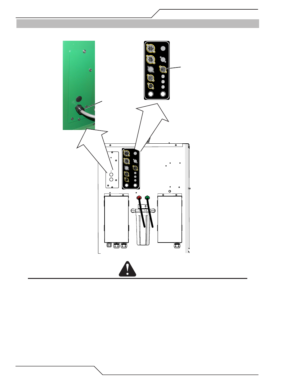
3.12 Connect TSC-3000 Cable and DMC-3000 Fiber Optic Cable to CCM
1. Remove the bottom plastic plug in the CCM at the rear of the Power Supply.
COOLANT
RETURN SUPPLY
Art # A-11991
USER INPUT
HEIGHT CONTROL
F1 - 8A SB 230 VAC
F2 - 8A SB 230 VAC
CB4 - 5A 120 VAC
CB3 - 5A 24 VAC
CB2 - 5A 120 VAC
J55 - GCM
J15 - CNC
J59 - RAS
J70 - HE
J54 - TSC /COMM
USER INPUT
HEIGHT CONTROL
F1 - 8A SB 230 VAC
F2 - 8A SB 230 VAC
CB4 - 5A 120 VAC
CB3 - 5A 24 VAC
CB2 - 5A 120 VAC
J55 - GCM
J15 - CNC
J59 - RAS
J70 - HE
J54 - TSC /COMM
TSC-3000 Cable
DMC-3000 Fiber
Optic Cable
CAUTION
Avoid kinking, twisting, or bunching the fiber optic cable. The cable can be damaged by being forced into tight-radius
turns.
2. Remove outer thin nut from through hole protector at one end of Fiber Optic Cable (L) that connects between the CCM
portion of the Power Supply and the DMC-3000.
3. Feed the Fiber Optic Cable plug and wires through the hole where the plastic plug was removed labeled GCM/DMC and
slide the thin nut back over the Fiber Optic Cable.
4. Secure the thin nut on the through hole protector so both nut faces are tight against the sheet metal inside and out.
5. Plug the Fiber Optic Cable into the PCB as shown below. Make sure the locking tabs are engaged. Fiber Optic for the
DMC-3000 goes into the lower pair of fiber optic receptacles (U31 & U37).