06 connect input power and ground cables, Connect input power and ground cables -5, Ultra-cut 400 xt – Tweco 400 XT Ultra-Cut Plasma Cutting System With Automated Gas Control User Manual
Page 27
ULTRA-CUT 400 XT
Manual 0-5306
INSTALLATION
3-5
3.06 Connect Input Power and Ground Cables
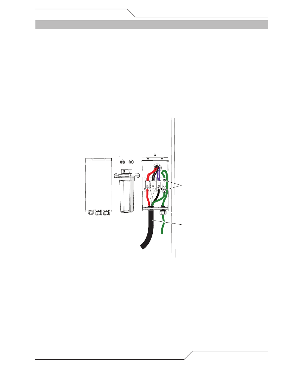
Connect Input Power and System Ground Cables
1. Remove the input power cover to the right of the coolant filter at the rear of the power supply. To do this remove the two
screws then lift up and pull away.
2. Carefully cut back the outer sheath on the primary input power cable to expose the individual wires. Cut back the insula-
tion on the individual wires. Route the cable upward through Input Power Port at the bottom of the panel. There are 2
extra plates included at the cable entrance. Discarding one or both allows changing the opening size for larger cable/
strain relief.
3. Install stripped end of 3 phase wires into the terminal block L1, L2 and L3 and connect the individual cables as shown.
4. Connect the power cable ground wire to the ground terminal block.
5. Route a system ground cable (F1) through the last opening in the connections cover support panel next to the input power
cable. Connect the cable to the ground terminal block on the power supply rear panel. Refer to the Ground Connections
Section for full details and procedures on proper system grounding.
Input Power
Ground Terminals
Art # A-11970
F1 Ground