Ultra-cut 400 xt – Tweco 400 XT Ultra-Cut Plasma Cutting System With Automated Gas Control User Manual
Page 30
ULTRA-CUT 400 XT
3-8
INSTALLATION
Manual 0-5306
NOTE
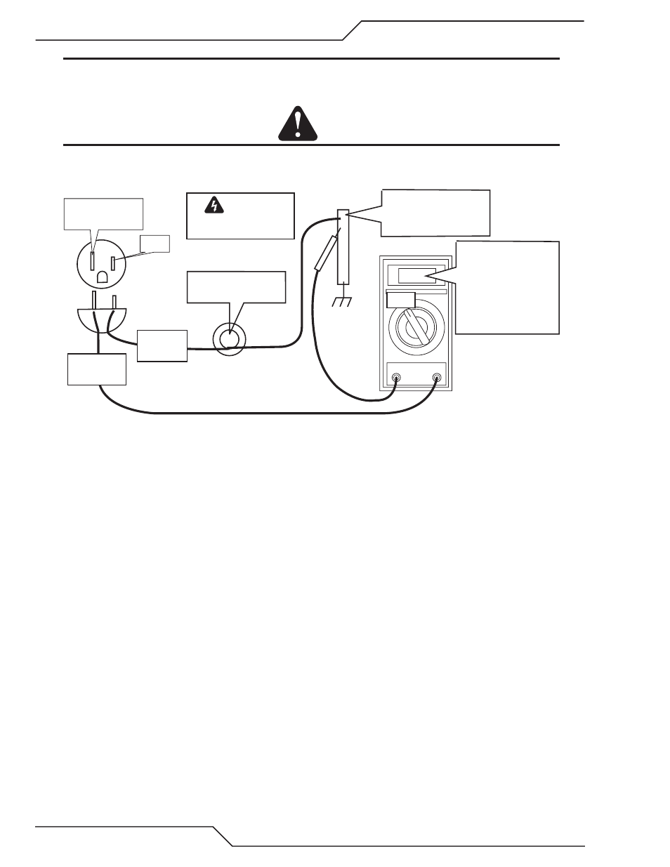
Ideally, a properly installed ground rod will have a resistance of three ohms or less.
To test for a proper earth ground, refer to the following diagram. Ideally, the reading on the multimeter should be as shown.
CAUTION
No other connections should be made at the ground rod being tested.
This test assumes the 115 or 230 VAC source neutral is connected to the utility earth ground.
Art # A-07252
WARNING
Use extreme caution. This
test uses live voltage.
NEUTRAL
Earth Grounded
HOT
On 115V AC Line:
3VAC = 3 ohms
1VAC = 1 ohm
On 230V AC Line:
1.5VAC = 3 ohms
0.5VAC = 1 ohm
Ground Rod
with other
connections removed
100W Incandescent
light bulb*
* Can replace light bulb with
a 100w resistor.
Use 100 ohm for 115VAC.
Use 500 ohm for 230VAC
NEUTRAL
PROBE
VAC
HOT
PROBE
Ground Testing
2. Increasing the ground rod length beyond 20 - 30 ft (6.1 – 9.1 m) does not generally increase the effectiveness of the ground
rod. A larger diameter rod which has more surface area may help. Sometimes keeping the soil around the ground rod moist
by continuously running a small amount of water into it will work. Adding salt to the soil by soaking it in salt water may also
reduce its resistance. You may also try a chemical ground rod devise. When these methods are used, periodic checking of
the ground resistance is required to make sure the ground is still good.
D. Routing Of Torch Leads
1. To minimize RF interference, position torch leads as far as possible from any CNC components, drive motors, control cables,
or primary power lines. If cables have to pass over torch leads, do so at an angle. Do not run the plasma control or other
control cables in parallel with the torch leads in power tracts.
2. Keep torch leads clean. Dirt and metal particles bleed off energy, which causes difficult starting and increased chance of RF
interference.