Ultra-cut 400 xt – Tweco 400 XT Ultra-Cut Plasma Cutting System With Automated Gas Control User Manual
Page 176
ULTRA-CUT 400 XT
A-52
APPENDIX
Manual 0-5306
Art # 12307
1
2
3
4
5
6
7
8
9
10
11
12
13
14
15
16
17
18
19
20
21
22
23
24
25
26
27
28
29
30
31
32
33
34
35
36
37
38
39
40
J23
TO RELAY BOARD
1
2
3
4
5
6
7
8
9
10
11
12
13
14
15
16
17
18
19
20
21
22
23
24
25
26
27
28
29
30
31
32
33
34
35
36
37
38
39
40
J4
From I/O PCB
24VDC_SW
D21
GREEN
D23
RF ON
1
5
3
4
K2
RAS CONTROL
120
VA
C
120 VAC to RAS
1
2
3
4
5
6
7
8
9
10
11
12
13
14
15
16
J8
120
VA
C
R
ET
120 VAC_1
From J9-1
120 VAC_RET
From J9-7
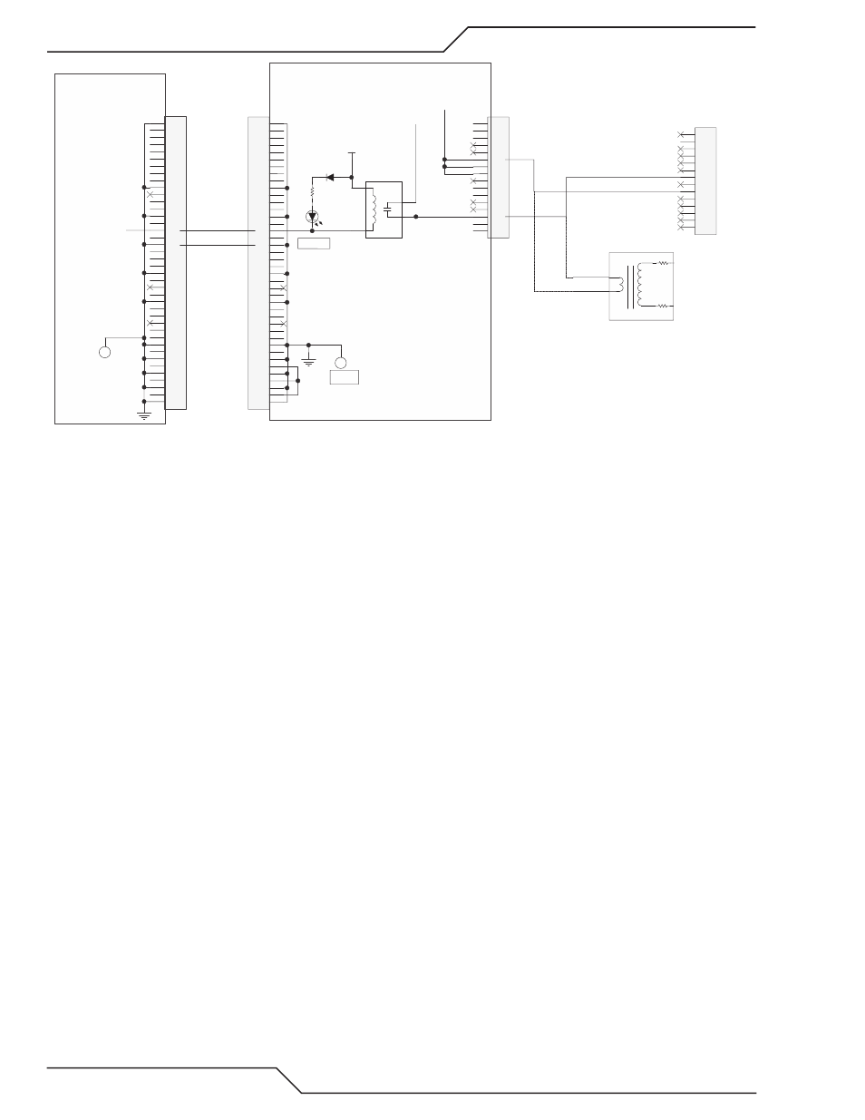
CCM I/O Board
Relay & Interface Board
1
2
3
4
5
6
7
8
9
10
11
12
13
14
J59 - RAS
(98)
(99)
T2
120 / 6000 VAC
(98)
(99)
6.5K 1W
6.5K 1W
AC200XT only
(Rear Panel)
TP1
GND
TP1
GND
/ RAS ON
8. If “ /RAS ON” signal is low on pin 16 of the 40 pin ribbon cable, relative to TP1 on the CCM I/O board, during the ignition
time then we need to determine if the Relay board is defective. If /RAS ON signal is not low the CCM or the 40 pin ribbon
cable may be defective.
a. If the Relay board RF ON LED, D23, is not on while the /RAS ON signal is low, then the Relay board is defective.
b. Is D23 is on, measure for 120 VAC on J8-3 to J8-11. If not present the Relay board is defective.
c. If 120 VAC is present at J8 during the ignition time go back and perform steps 2-4.
Troubleshooting Pilot Board problems.
1. The Pilot board is behind the CCM in the AC 300 XT and all Ultra-Cut XTs or on the upper section of the second inverter
module in an AC 200 XT and has two LEDs. The first one, D11, a green LED, indicates the board has bias power and
should be on all the time when the unit is turned on. The second LED, D2, also green, is on when the pilot is enabled, that
is the pilot IGBT switch is turned on. The pilot is enabled near the end of preflow time and remains on until the transfer
is established or for 15 seconds after which a 102 code is displayed. If D2 performs as expected you know the CCM,
Relay board and work current sensor are not causing the problem.
2. If D11 on the Pilot board is not on check if the 10 pin ribbon cable is connected between the Pilot board (J42) and the
Relay board (J3). Measure for 24 VDC on the Pilot ribbon cable test connector pin 2 (+) and pin 10 (-). If 24V is present
and neither D11 nor D2 lights then the Pilot board may be defective. Pilot board end of the ribbon cable could also be
the cause.
What should happen on the Relay board is LEDs D12, work Current Detected & D11, Pilot Current Detected should both be
off. When you apply START after 2 seconds (Preflow time) D7, Pilot Enable, should come on. Also D23, RF ON, should
come on indicating the Arc Starter is being enabled. Normally D23 would only be on for a moment until pilot current
is detected. Then D11 would be on (and D23 off) until arc transfer or pilot timeout (15 sec.) Since a pilot has not been
detected D11 should not come on.
3. If the work current sensor is defective it could be telling the relay board (and thus the CCM) that there is already a trans-
ferred arc so no need for pilot. D12, a green LED on the Relay board, is on if work current is detected. If D12 is not on
skip to step 5, otherwise disconnect J1, the work sensor connector. If D12 is still on the Relay board is defective.
4. If D12 goes out when J1 is disconnected, plug it back in and measure voltage from TP1 (common) to J1-1, should be
positive 12-15VDC. Now measure J1-2, should be negative 12-15VDC. Now measure J1-3, should be 0 +/- 0.05V. If
any of these are wrong disconnect J1 and measure again (on the relay board, not the harness). If still wrong the relay
board is defective. Otherwise it’s the work sensor.