11 handling and installation of fiber optics, Handling and installation of fiber optics -10, Ultra-cut 400 xt – Tweco 400 XT Ultra-Cut Plasma Cutting System With Automated Gas Control User Manual
Page 32
ULTRA-CUT 400 XT
3-10
INSTALLATION
Manual 0-5306
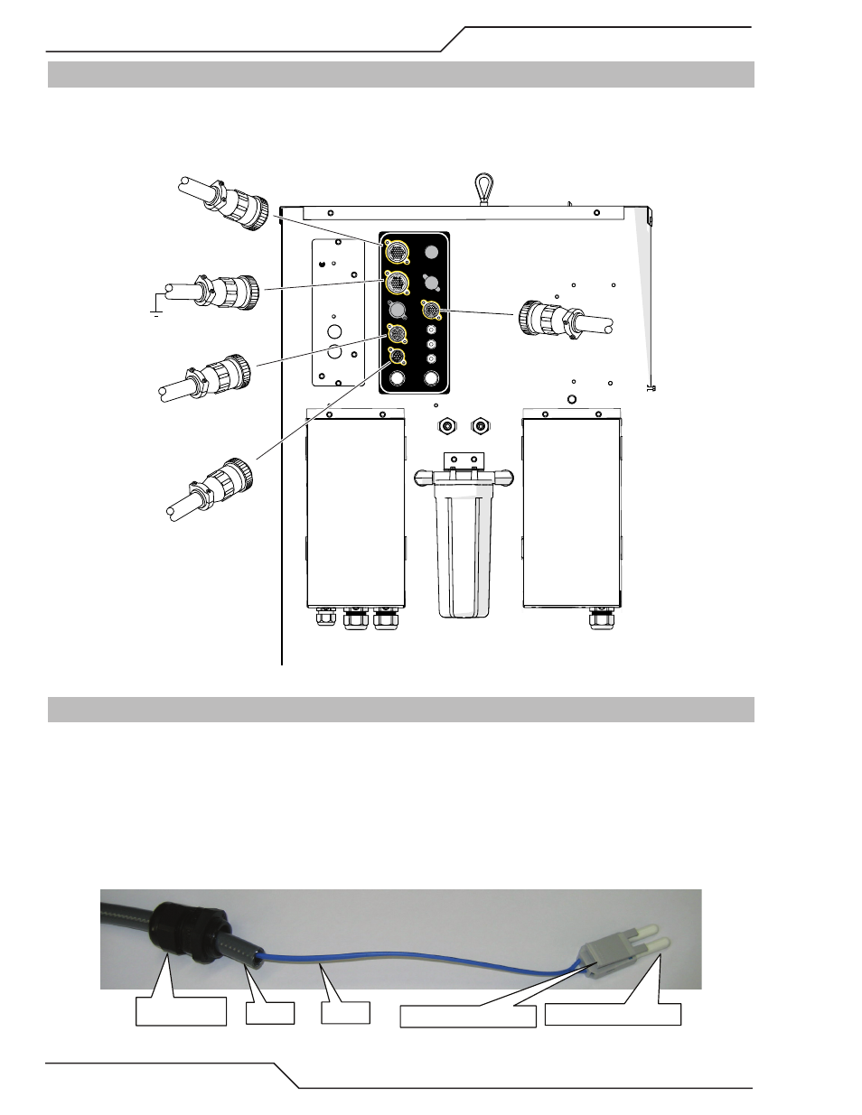
3.10 Connect Cables for CNC, Remote Arc Starter, GCM and HE 400
1. Connect one end of each cable to the power supply.
2. Connect the other end of the CNC cable to the CNC device
.
3. The CNC cable shield must be attached to ground at the CNC end.
USER INPUT
HEIGHT CONTROL
F1 - 8A SB 230 VAC
F2 - 8A SB 230 VAC
CB4 - 5A 120 VAC
CB3 - 5A 24 VAC
CB2 - 5A 120 VAC
J55 - GCM
J15 - CNC
J59 - RAS
J70 - HE
J54 - TSC /COMM
Art # A-11971
J15 To CNC Control
J59 To Remote
Arc Starter
J55 To GCM
J70 To Heat
Exchanger
J54 TSC/
Comm
3.11 Handling and Installation of Fiber Optics
General Information
This kit is for proper handling and installation of Fiber Optic Cables used in Thermal Dynamics Ultra-Cut
®
and Auto-Cut O2
®
automated gas boxes and Gas Control Modules.
Fiber Optic cable is used in place of wire because it offers far superior immunity to electrical noise but it is more delicate and
requires careful handling. With fiber optics, electrical signals are converted to light with a transmitter LED. The light passes down
the fiber where it is converted back to an electrical signal at the receiver end. Any damage to the fiber from sharp bends or pulling
that stretches the fiber can reduce it’s ability to transmit light. We run the fiber inside a hose for most of its length to protect it
from abrasion, burning from hot metal or sharp bends but the ends are exposed and must be handled with care.
Hose
Strain Relief
Fiber
Connector with Latch
Protective End Covers
Art # A-09416