Ultra-cut 400 xt – Tweco 400 XT Ultra-Cut Plasma Cutting System With Automated Gas Control User Manual
Page 172
ULTRA-CUT 400 XT
A-48
APPENDIX
Manual 0-5306
External or CNC Plasma Enable D2, CNC PLASMA ENABLE LED, is not on.
• LED D2 on the CCM will be on if this input is satisfied either with the jumper on TB1- 1 & 2 or an external or CNC
switch. If the jumper is in place and the LED is not on, the CCM is most likely defective.
• If the jumper at CCM TB1-1 & 2 has been removed to use an external switch, install a jumper as a test. If D2 illuminates
the problem is with the switch or it’s wiring.
• If Plasma Enable is wired through the CNC cable remove the cable and jumper J15 pins 25 & 26. If D2 still not on
there may be a problem in the wiring inside the power supply.
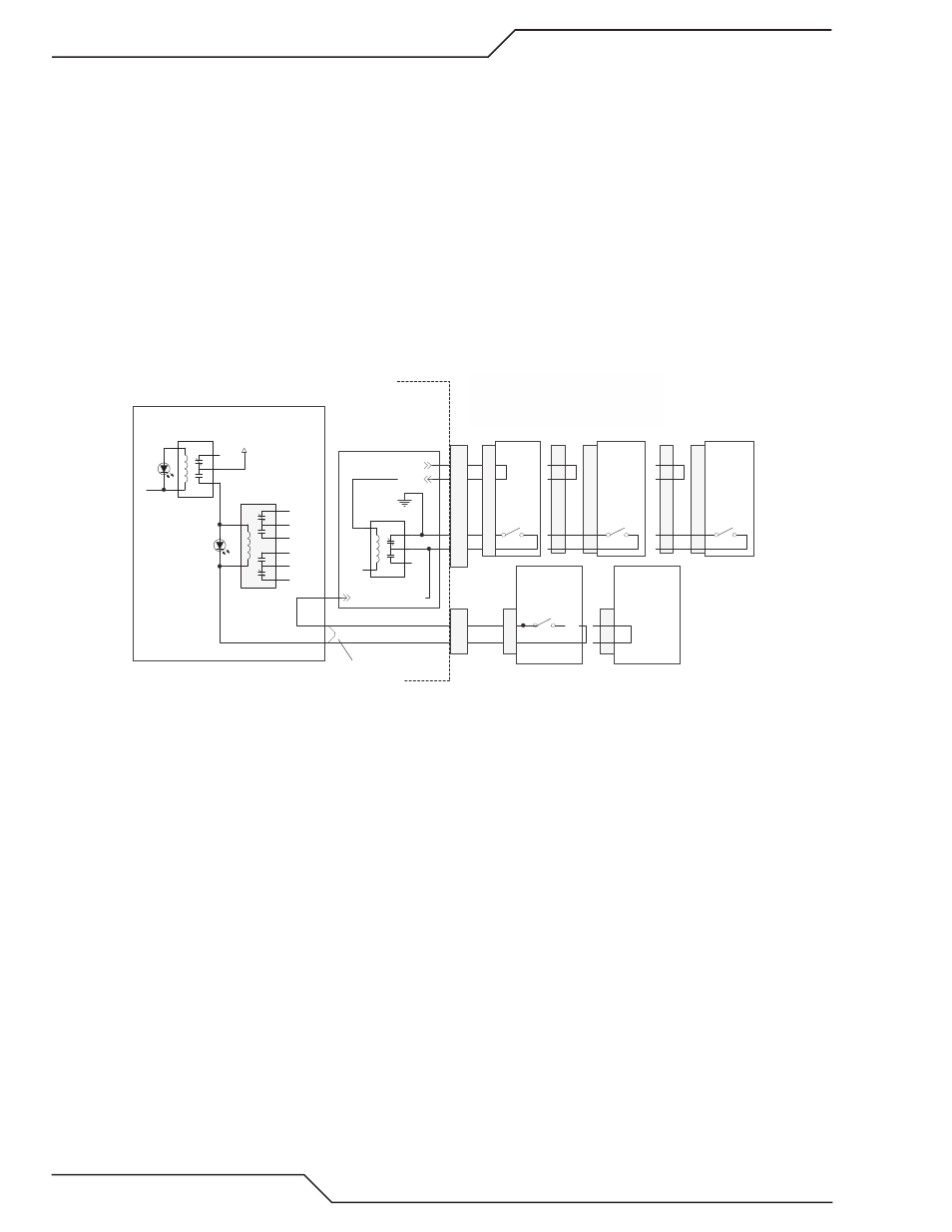
Plasma Enable from Gas Control or TSC 3000
If the External or CNC Plasma Enable is satisfied, D2 is on, a relay K7 on the CCM I/O PCB energizes supplying +15V to
another relay K1 on the I/O board. An active low signal, /Plasma Enable-HMI, comes from TSC 3000 Plasma Enable switch
via the Relay PCB or if TSC 3000 is not installed the signal originates on the Relay PCB. This signal applies ground to the K1
relay energizing it and lighting the LED, D3 on the I/O board. K1’s contacts go back to the Relay board and the Gas control
connector J55 to allow turning on relays and solenoids on those devices. The AC 200 XT does not use the separate Gas
Control or the TSC 3000.
Art # 12304
1
5
3
2
4
K7
1
8
4
2
6
7
3
5
PLASMA ENABLE
K1
/PLASMA ENABLE - HMI
GND
24 VAC
24 VAC
TSC 3000
RELAY PCB
1
5
3
2
4
PLASMA ENABLE - CNC
K6
+15VDC
GREEN
D3
PS_ENABLE
To
Relay
PCB
To Gas
Control
CCM I/O PCB
GREEN
D2
Plasma Enable SW
GCM 2010
(or jumper in
other gas controls)
-1
-3
-5
-6
J54
J55
XT Power Supply
Simplified schematic, all connectors are not shown.
Refer to unit schematics for details.
J61
J56
-1
-2
Jumper in
AC 200 XT
J26-6
J26-7
GCM 1000 XT
J56
J54
When the circuit between J54-1 & 3 is closed (jumper,
etc.) K7 is energized and requires a Plasma Enable SW
or equivlant to enable the plasma.
With J54-1 & 3 open K7 is denergized and it's NC
contacts complete the Plasma Enable-HMI circuit.
-1
-2
-2
-1
-5
-6
-3
-1
-5
-6
-3
-1
(AC 300 XT
DMC 3000)
J25
-15
-22
J30
-20
-25
Plasma
Enable
SW
iCNC
XT 2 &
XT 242
J54
-5
-6
-3
-1
iCNC
XT 211
HMI PLASMA
ENABLE BYPASS
If a TSC 3000 is not connected or unit is an Auto-Cut, K7 on the Relay PCB is de-energized and GND is connected through
its normally closed contacts. If the TSC is connected, 24 VAC through a jumper in the TSC 3000 energizes K7, opening its
NC contacts and now GND connects through the TDC 3000 Plasma Enable switch. The GND obtained by either path passes
through the GCM 2010 Plasma Enable switch or through a jumper (J56-1 to J56-2) present in the other gas controls (GCM
1000 XT or DMC 3000) and is connected to the coil of K1 on the I/O PCB. If the CNC Plasma Enable is also active (D2 is
on) +15V will be connected to K1’s coil through the relay K7 on the I/O PCB. This energizes K1 and turns on D3, Plasma
Enable LED. The contacts of K1 go back to the Relay board and to the Gas control to enable power to connect to relays and
solenoids in those items.
Troubleshooting:
1. If both D2 and D3 are on and you still have 101 fault replace the CCM. Otherwise go to step 2 except if it’s an AC 200
XT skip to step 4.
2. If D3 is not on and there is a TSC 3000 in use remove its cable from J54. K7 on the Relay board will de-energize and
satisfy the Plasma Enable to K1. If D3 is now on problem was in the TSC 3000 or its cable. Otherwise reconnect the
cable.
3. For an Ultra-Cut with DFC 3000 or GCM 2010 or an Auto-Cut 300 with a GCM 1000 XT remove the cable from J55
the gas control connector and jumper pins 1 & 2. If D3 is on now problem is in the Gas Control or its cable. If D3
still not on replace the Gas Control cable.
4. If neither of the above steps works, on the CCM I/O board, jumper J26-7 to GND (TP1 on I/O). If D2 is on and D3
still does not light then replace the CCM.