Ultra-cut 400 xt – Tweco 400 XT Ultra-Cut Plasma Cutting System With Automated Gas Control User Manual
Page 180
ULTRA-CUT 400 XT
A-56
APPENDIX
Manual 0-5306
OT FLT (D14, OT FLT, Inverter Control and Fault board)
• Inverter over temperature lights LED D14 on the Inverter Control and Fault board and will latch the fault signal and it’s
LED but also has its own separate fault so that will be reported as a code in the range of 253-258 or 259-264.
PWR Present
• When power is first applied to the inverter (contactor closed) CCM checks for presence of the +12V bias on the Inverter
Control and Fault board. If not present will set codes in the range of 265-270.
IS_ID (A, B, or C)
VAC_SEL (A or B)
201
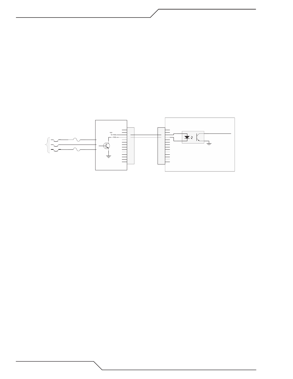
Missing AC Phase
The System Bias Supply board contains circuits to detect if one of the 3 AC input phases is missing. Along with that it can
also detect if the AC voltage is too low or too high. Three phase voltage is supplied from the input terminals through the ON/
OFF Switch / circuit breaker CB1 to the System Bias board. The System Bias can operate on any 2 of the 3 phases to supply
control power and fault detection.
1
2
3
4
5
6
7
8
9
10
11
12
13
14
J62
1
2
3
4
5
6
7
8
9
10
11
12
13
14
J27
GND
+V
1
2
4
3
HCPL-817
U?
Missing Phase a
Missing Phase b
GND
To CPU PCB
J29-16
Missing Phase
I/O PCB
SYSTEM BIAS PCB
CB1
ON / OFF
F2
F1
J60-9,18
J60-5,14
J60-1,10
3 phase AC
Art # 12310
Normally when the phase is not missing the transistor is on which turns on the opto-isolator making the signal “Missing
Phase” low.
Causes for 201, missing phase code. Codes are displayed two different ways, with an “L” meaning “Latched” or “Last”, before
the number meaning it was a problem but isn’t right now or with an “E” meaning the problem exists now.
L201 :
Most likely cause is an intermittent problem with the incoming power or possibly a loose connection on the power cord at
the back or the Ultra-Cut or Auto-Cut plasma supply.
E201:
• Phase missing from the wall fuse box, blown fuse.
• F1 or F2, 8A 500V slow blow fuses blown.
• CB1 one phase open.
• System Bias board defective.
• I/O board defective.
Troubleshooting:
1. System Bias board has a red LED, D3, that lights if it detects a missing phase. If D3 is on, check J60 for all 3 phases.
a. If all 3 phases are not present at J60 check for incoming power, then the F1 & F2 fuses. Finally the CB1.
b. If all 3 phases present and about equal voltage then change the System Bias board.
2. If D3, Missing Phase LED, is not on check for voltage at J27-3 & 4 on the CCM. Normal voltage, with no missing phase,
at J27 (or J62 on the System Bias board) pin 3 and pin 4, relative to I/O PCB ground. (TP1) should be between 10-14VDC
with pin 3 being a couple volts higher than pin 4. If this is normal, problem may be in the CCM.
3. If the voltage at J27-3 & 4 is higher than 10-14VDC and up to 20-24VDC, make the same measurement at J62 pin 4. If
still high there and you have confirmed all 3 phases are present at J60 then the System Bias is defective.
4. If the voltage at J62-4 is not high the wires between J27 and J62 may be broken.