Installation instructions – Brandmotion 1008-9527-V2 User Manual
Page 38
INSTALLATION INSTRUCTIONS
9527 Instructions 6-18-12 F series-1 (1).doc 38 of 38
Section 11E: Reference – Vehicles with Sync Microphone in Mirror
Follow the steps on this page only for auto dimming inside rear view mirror with built in Sync microphone.
74. Splice the supplied interior harness to the vehicle mirror harness by following the next ten steps and Diagram E.
Note: Isolate the black, green and pink wires at the white 6 pin connector end of the supplied interior harness with
electrical tape as they will not be used.
• Splice the black ground wire from the supplied interior harness black 16 pin connector end to the wire in pin 10
of the vehicle mirror harness connector.
• Splice the green reverse wire from the supplied interior harness black 16 pin connector end to the wire in pin 3
of the vehicle mirror harness connector.
• Splice the pink ignition wire from the supplied interior harness black 16 pin connector end to the wire in pin 1 of
the vehicle mirror harness connector.
• Splice the orange positive (+) auto dimming wire from the supplied interior harness black 16 pin connector end
to the wire in pin 8 of the vehicle mirror harness connector.
• Splice the white negative (-) auto dimming wire from the supplied interior harness black 16 pin connector end to
the wire in pin 7 of the vehicle mirror harness connector.
• Splice the red positive (+) compass wire from the supplied interior harness black 16 pin connector end to the
wire in pin 6 of the vehicle mirror harness connector.
• Splice the yellow negative (-) compass wire from the supplied interior harness black 16 pin connector end to the
wire in pin 2 of the vehicle mirror harness connector.
• Splice the yellow open wire from the microphone harness (supplied separately) to the wire in pin 4 of the
vehicle mirror harness connector.
• Splice the black ground wire from the microphone harness (supplied separately) to the wires in pins 5 and 10 of
the vehicle mirror harness connector.
• Splice the blue 12V positive (+) wire from the microphone harness (supplied separately) to the wire in pin 1 of
the vehicle mirror harness.
• Cover all connections with electrical tape or heat shrink.
75. Place the microphone in a convenient place on A-pillar or in headliner.
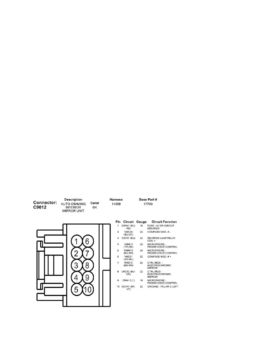
Auto Dimming With Built In Sync Microphone Mirror Pinout DIAGRAM E
Supplied
Interior
Harness
Wire
Color
1 Pink
2 Yellow
3 Green
4
5
6 Red
7 White -
8 Orange +
9
10 Black
Microphone
Supplied
Harness
Wire
Color
1 Blue +
2
3
4 Yellow -
5 Black
6
7
8
9
10 Black