Installation instructions – Brandmotion 1008-9527-V2 User Manual
Page 13
INSTALLATION INSTRUCTIONS
9527 Instructions 6-18-12 F series-1 (1).doc 13 of 38
Section 7C: Wiring for vehicles with 16-pin connector
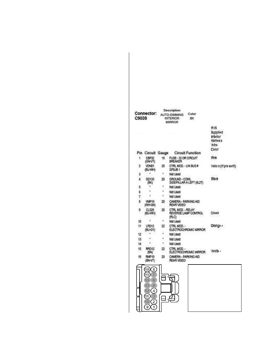
38. On the supplied interior harness, near the black
16 pin connector, locate the seven loose wires
(Note: Isolate the red wire with electrical tape as
it will not be used). Using Connector C9039
pinout diagram opposite, splice the remaining six
wires to the vehicle mirror harness wires where
the mirror connector was removed in step 35 as
follows:
•
Splice the supplied interior harness black
ground wire to the loose vehicle mirror
ground wire that was in pin 4.
•
Splice the supplied interior harness green
reverse wire to the loose vehicle mirror
reverse wire that was in pin 9.
•
Splice the supplied interior harness pink
ignition wire to the loose vehicle mirror
ignition wire that was in pin 1.
•
If populated, splice the supplied interior
harness yellow wire to the loose vehicle
mirror wire was in pin 2.
•
Splice the supplied interior harness orange
auto dimming (+) wire to the loose vehicle
mirror auto dimming (+) that was in pin 11.
•
Splice the supplied interior harness white
auto dimming (-) wire to the loose vehicle
mirror auto dimming (-) wire that was in pin
15.
39. If you removed the compass circuit board,
per section 7A, on the supplied interior
harness, near the white 6 pin connector, locate
the five short wires. (Note: Isolate the red wire
with electrical tape as it will not be used). Using
Connector C9039 pinout diagram opposite, splice
the remaining four wires to the vehicle mirror
harness connector removed in Step 35 as
follows:
•
Splice the supplied interior harness black
ground wire to the vehicle mirror connector
ground wire. (pin 4).
•
Splice the supplied interior harness green
reverse wire to the vehicle mirror connector
reverse wire. (pin 9).
•
Splice the supplied interior harness pink
ignition wire to the vehicle mirror connector
ignition wire. (pin 1)
• If populated, splice the supplied interior
harness yellow wire to the vehicle mirror
connector wire that supplies pin 2.
•
If you did not remove the compass circuit
board, isolate the five loose wires with
electrical tape, as they will not be used.
NOTE: If reverse signal does not exist in Pin 9 of 16-
pin mirror C9039 connector (see diagram
opposite), then follow directions in Section 8 to
connect reverse.
NOTE: Circuit colors
shown may vary
depending on model
and year. Verify pin
locations and check
circuit for proper
function using a digital
volt-ohm meter.