Installation instructions – Brandmotion 1008-9527-V1 User Manual
Page 16
INSTALLATION INSTRUCTIONS
9527 Ford Flex Instructions 7-27-12.doc
16 of 18
Section 8: Ignition, Reverse and Ground Locations –
Vehicles with Inside Rear View Mirrors without Auto Dimming
(if required)
Follow these steps only if vehicle does not have an auto dimming inside rear view mirror
.
61. Remove the driver side door sill plate with a trim
tool, just disengaging the two clips from the sheet
metal and remove driver side kick panel.
62. Isolate the seven wires near the black 16-pin
mirror connector on the supplied interior harness with
electrical tape along with the red and yellow wires
near the black 6-pin connector.
63. Route the supplied interior harness green, pink,
and black wires along the vehicle dash harness.
Secure using wire ties wherever possible at 2 inch
intervals.
64. Splice the green reverse wire from the supplied
interior harness black 6-pin connector end to the wire
listed below. Cover the connection with tape or heat
shrink tubing.
65. Attach the black ground wire eyelet from the
supplied interior harness black 6-pin connector end to
sheet metal in the driver side kick panel with a screw
using an 8mm socket.
66. Splice the pink ignition wire from the supplied
interior harness black 6-pin connector end to the wire
color listed below. Solder and cover the connection with
tape or heat shrink tubing.
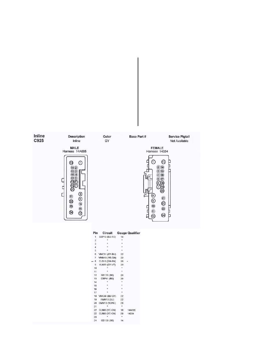
Reverse Lamp Relay Location – Connector C925 – 2009-2012 Ford Flex
Pin Circuit Function Supplied Interior
Harness Color
8 Relay – Reverse Lamps
Green
12 Ground – A Pillar Left
Black
13 Fuse – 41 or Circuit Breaker
Pink (12V + Ignition)
24 Ground – Pillar A Left
Black