Rockwell Automation MPAS Integrated Linear Stages User Manual
Page 46
46
Rockwell Automation Publication MP-UM001D-EN-P - September 2013
Chapter 6
Configuration Guidelines
Motor Feedback
Feedback Type
TTL with Hall
Cycles 50
Per Millimeter
Conversion
Positioning Mode
Linear
Conversion Constant
200 drive counts / 1.0 mm
5080 drive counts / 1.0 in.
Hookup
(1)
Test Increment
70 mm, min for Ultra3000 drive
20 mm Kinetix 2000 drive
20 mm Kinetix 6000 drive
2.76 in. min for Ultra3000 drive
0.787 in. Kinetix 2000 drive
0.787 in. Kinetix 6000 drive
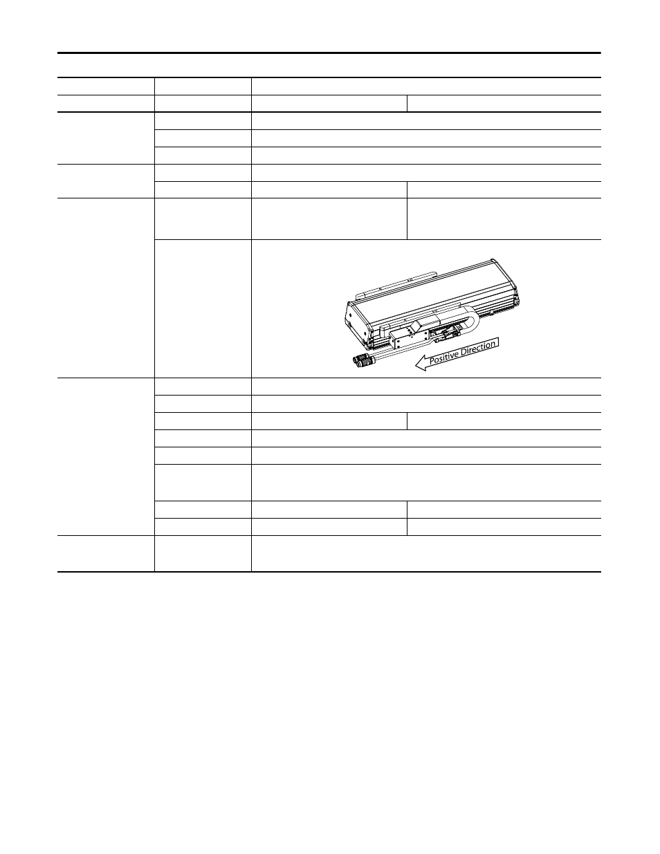
Drive Polarity
Positive (see definition)
Homing Mode Active
Position 0
(or
programmable)
Offset
5 mm, min
0.2 in., min
Sequence Torque
Level-to-Marker
Direction Reverse
Bi-directional
Torque Level
80%, min
Greater if the system friction, force, or weight exceeds 80% of the Continuous Force Rating at any point in the range
of motion
Speed 50 mm/s
1.97 in/s
Return Speed
10 mm/s
0.39 in/s
Software or Hardware Limits
Negative Limit
or
Positive Limit
Use Motion Analyzer to determine the maximum stopping distance in your application
(1) The Command and Feedback test, accessed from the Hookup tab, does not verify the Hall Sensor wiring to a Kinetix 2000 or a Kinetix 6000 drive. The wire colors and continuity for the Hall signals must be
manually verified.
Axis Properties Tab
Parameter
Entry/Selection, with applicable distance unit settings
Millimeters
Inches
(+)
(-)
(+)
(-)