Rockwell Automation MPAS Integrated Linear Stages User Manual
Page 36
36
Rockwell Automation Publication MP-UM001D-EN-P - September 2013
Chapter 4
Mounting and Connecting
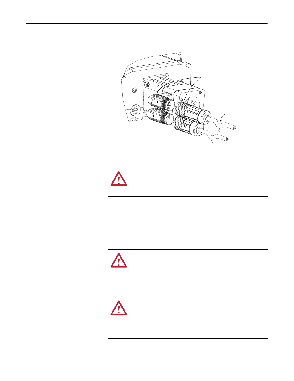
3. Form a drip loop in each cable at a point directly before it attaches to the
motor.
4. Attach the feedback cable, and the combination power and brake cable to
the motor.
a. Carefully align each cable connector with the respective motor
connector as shown in the diagram.
b. Do not apply excessive force when mating the cable and motor
connectors.
If the connectors do not go together with light hand force, realign and
try again.
ATTENTION: Do not connect or disconnect the motor feedback cable, or the
power and brake cable while power is applied to them.
Inadvertent pin connections can result in unexpected motion or result in
irreversible damage to the components.
ATTENTION: Be sure that cables are installed and restrained to prevent uneven
tension or flexing at the cable connectors. Excessive and uneven lateral force at
the cable connectors can result in the connector’s environmental seal opening
and closing as the cable flexes.
Failure to observe these safety procedures could result in damage to the motor
and its components.
ATTENTION: When installing a threaded DIN cable with a M4 designation, an
O-ring must be installed in the groove immediately adjacent to the body of the
linear thruster connector. This O-ring dampens the effects of vibration at the
cable-to-linear thruster connection.
Cables requiring O-rings include 2090-XXNFMF-Sxx (standard, non-flex)
feedback cables.
Align Flat Surfaces
Power/Brake
Connector
Feedback
Connector
Drip Loop
in Cable