Rockwell Automation 6012DB PowerFlex Medium Voltage Variable Frequency Drive User Manual
Page 98
98
Rockwell Automation Publication 6000-UM001B-EN-P - October 2014
Chapter 5
Preventative Maintenance and Component Replacement
Drawout Power Module
1.
Remove and retain the M12 bolt, washer, lock washer, and nut from the
top and bottom of the fuse.
2.
Remove the fuse from between the fixed bracket and the power cable and
bus bar.
3.
Install the new fuse, and the hardware in reverse order of removal.
4.
Torque all hardware to specifications (see
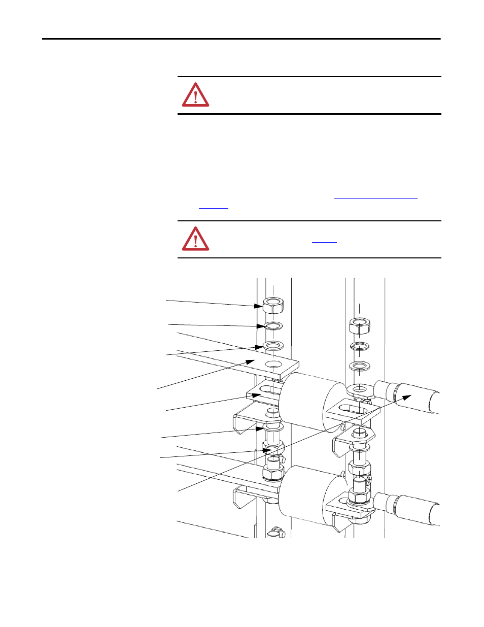
Figure 35 - Exploded View of Fixed-mounted Power Module Fuse
ATTENTION: Ensure the input circuit breaker feeding the drive is open. Lock out
and tagout the input circuit breaker before performing any work on the drive or
bypass units.
ATTENTION: The hardware connecting the Drawout Power Modules MUST be
reinstalled facing up, as shown in
. Failure to install the hardware in
this manner will affect clearance distance between bolts and can cause an arc.
Washer
Lock washer
M12 x 30 Bolt
Fuse
Washer
Nut
Power Cable
Bus bar