Rockwell Automation 6012DB PowerFlex Medium Voltage Variable Frequency Drive User Manual
Page 92
92
Rockwell Automation Publication 6000-UM001B-EN-P - October 2014
Chapter 5
Preventative Maintenance and Component Replacement
3.
Remove the Output Copper Bars that connect adjacent Power Modules
(
If the Power Module is at the end of a row, remove the VSB and Motor
cable instead of an output copper bus.
4.
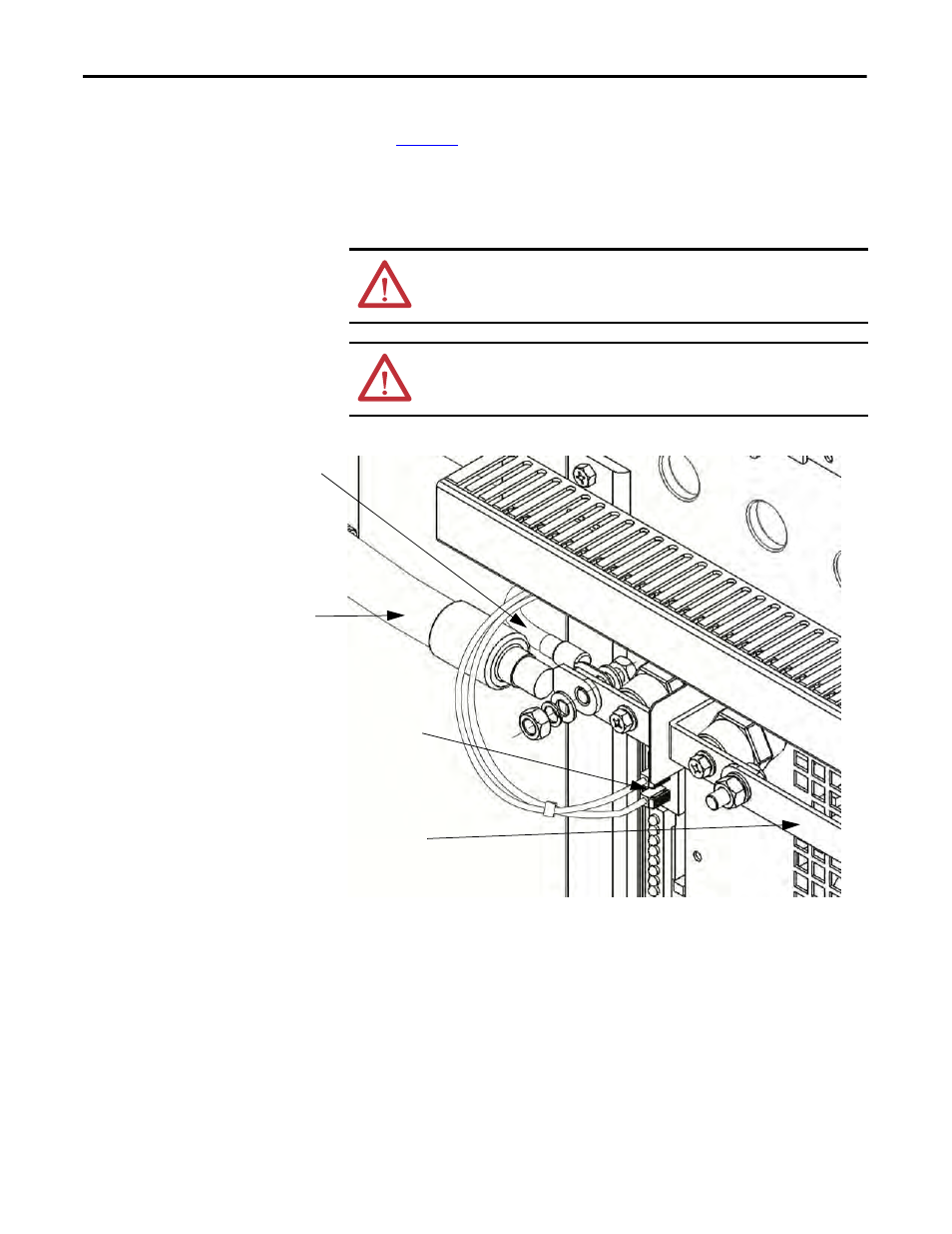
Disconnect the fiber optic cables.
Figure 31 - Close up of Fiber Optic Location and Power Cables
5.
Carefully withdraw the Power Module.
6.
Install the new Power Module in reverse order of removal.
ATTENTION: When removing the fiber optic cables, be careful to prevent the
cables from straining or crimping as the resulting loss in light transmission will
impact performance.
ATTENTION: Minimum bend radius permitted for the fiber optic cables is 50
mm (2.0 in.). Any bends with a shorter inside radius can permanently damage
the fiber-optic cable.
Motor Cable
VSB Cable
Output Copper Bar
Fiber Optic Cables