Replace power module – Rockwell Automation 6012DB PowerFlex Medium Voltage Variable Frequency Drive User Manual
Page 91
Rockwell Automation Publication 6000-UM001B-EN-P - October 2014
91
Preventative Maintenance and Component Replacement
Chapter 5
Replace Power Module
Table 7 - Power Module Specifications
Fixed-mounted Power Module
1.
Remove the positioning barriers from both sides of the Power Module.
2.
Disconnect the Three-phase Input Power Cables.
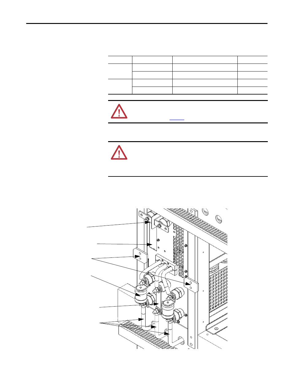
Figure 30 - Fixed-mounted Power Module Component Location
Type
Output Rating (Amps)
Dimensions (HxWxD), approx.
Weight, approx.
Fixed-mounted
≤150 A
420 x 180 x 615 mm (16.5 x 7.1 x 24.2 in.)
20 kg (44.1 lb)
151...200 A
420 x 260 x 615 mm (16.5 x 10.2 x 24.2 in.)
25 kg (55.1 lb)
Drawout
201...380 A
575 x 342 x 691 mm (22.6 x 13.5 x 27.2 in.)
40 kg (88.2 lb)
381...420 A
575 x 342 x 910 mm (22.6 x 13.5 x 35.8 in.)
50 kg (110.2 lb)
ATTENTION: Two people are required to handle the Power Modules. Always
handle the drawout Power Modules using the two recessed lifting handles on
both mounting rails (
Figure 33
).
ATTENTION: The high-voltage power source must be switched off before
replacing a Fixed-mounted Power Module. Wait for 20 minutes before opening
the cabinet doors. Verify that all circuits are voltage-free, using a hot stick or
appropriate high voltage-measuring device. Failure to do so may result in injury
or death.
Fuse
Positioning Barriers
Output Copper Bar (not shown)
Connection Location
Fiber Optic Cables Connection Point
Three-phase Input Cables
from Isolation Transformer
Center Jumper Bar