2 - drive system layout, Elevation drawings, Chapter 2 – Rockwell Automation 6012DB PowerFlex Medium Voltage Variable Frequency Drive User Manual
Page 17: Drive system layout, Chapter
Rockwell Automation Publication 6000-UM001B-EN-P - October 2014
17
Chapter
2
Drive System Layout
There are two basic power cell configurations offered in the PowerFlex 6000
product line. For a drive amperage rating
≤
200 A, a fixed-mounted power module
design is supplied. Fixed-mounted modules are shipped installed in the drive. For
a drive amperage rating of >200 A, a drawout power module design is supplied.
The PowerFlex 6000 drive is shipped in two sections, the Isolation Transformer
Cabinet and the Power Module/LV Control Cabinet. Refer to PowerFlex 6000
Medium Voltage Variable Frequency Drive Shipping, Handling, and Installation
Instructions
).
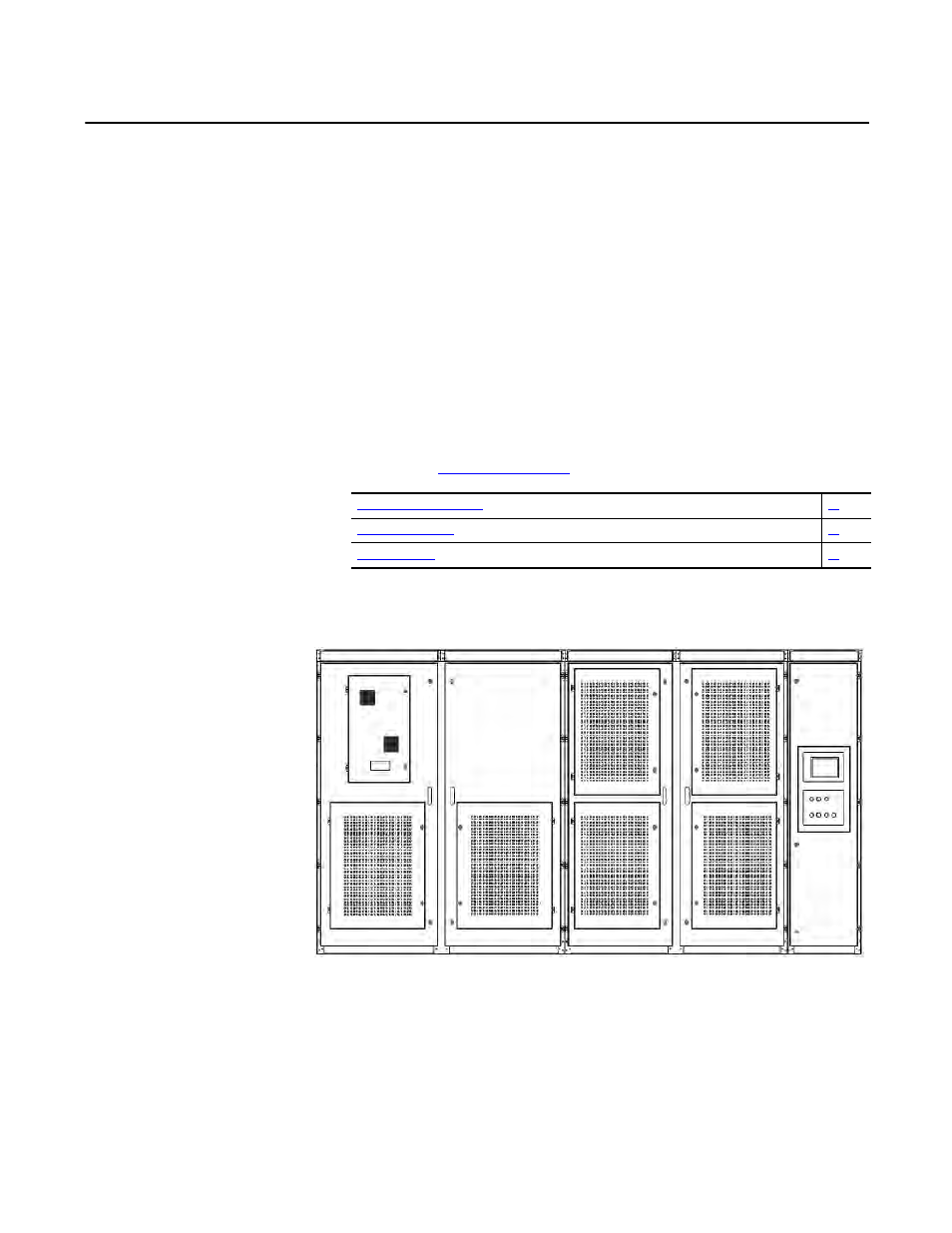
Elevation Drawings
Figure 7 - Fixed-mounted Power Module Drive Configuration
Isolation Transformer Cabinet
Power Module Cabinet
LV Control
Cabinet