Rockwell Automation 6012DB PowerFlex Medium Voltage Variable Frequency Drive User Manual
Page 85
Rockwell Automation Publication 6000-UM001B-EN-P - October 2014
85
Preventative Maintenance and Component Replacement
Chapter 5
Inspect Isolation Transformer Auxiliary Cooling Fans
When the drive is running, verify that each of the coil temperatures are the same
on the Isolation Transformer Temperature Monitor display. If there is more than
a 5 °C difference between the highest and lowest temperature, check the Isolation
Transformer Auxiliary Cooling Fans.
Test the Isolation Transformer Auxiliary Cooling Fans:
1.
Open the LV Control Door on the Isolation Transformer Cabinet.
Locate the correct circuit breaker(s).
2.
Disconnect the wires from the load side of the Isolation Transformer
Auxiliary Cooling Fan circuit breaker. Refer to Electrical Drawings.
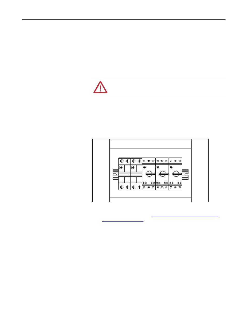
Figure 25 - Circuit Breaker Location on LV Control Door
3.
Connect 380V power to the wires to verify operation of the fans.
If a fan is not operational, see
Replace Isolation Transformer Auxiliary
Cooling Fans on page 86
.
Remove the power source and reconnect the wires to the circuit breaker.
ATTENTION: Verify that all circuits are voltage-free, using a hot stick or
appropriate high voltage-measuring device. Failure to do so may result in injury
or death.