Isolation transformer – Rockwell Automation 6012DB PowerFlex Medium Voltage Variable Frequency Drive User Manual
Page 20
20
Rockwell Automation Publication 6000-UM001B-EN-P - October 2014
Chapter 2
Drive System Layout
Isolation Transformer
The primary winding of the isolation transformer is rated for the voltage of the
distribution system. It is connected to the distribution system by the incoming
line power cables. The secondary windings of the isolation transformer are
connected to the inputs of the power modules. The secondary winding voltage is
typically 690V, to feed the low voltage power modules.
There are between 9 and 27 three-phase secondary side windings, dependent on
the motor voltage requirements. The phase relationship between the secondary
windings are optimized to provide the highest reduction of line side harmonics.
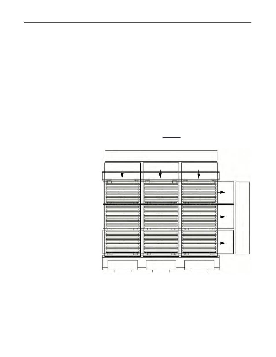
The isolation transformer’s three-phase primary coils are oriented C, B, and A
from left to right, as viewed from the front. The secondary windings are also
divided into three principal sections from top to bottom. The upper third are to
feed the power modules in the U output phase. The middle third are to feed the
power modules in the V output phase. The bottom third are to feed the power
modules in the W output phase (
Figure 11
).
Figure 11 - Isolation Transformer Primary and Secondary Winding Orientation
The secondary windings are brought out to corresponding vertical isolated stand-
offs on the body of the transformer (orientated C, B, and A from left to right as
viewed from the front).
PRIMARY WINDING INPUT
SEC
OND
A
RY WI
NDI
N
G
OUTPUT
C (L3)
B (L2)
A (L1)
U
V
W