Inspect isolation transformer – Rockwell Automation 6012DB PowerFlex Medium Voltage Variable Frequency Drive User Manual
Page 86
86
Rockwell Automation Publication 6000-UM001B-EN-P - October 2014
Chapter 5
Preventative Maintenance and Component Replacement
Replace Isolation Transformer Auxiliary Cooling Fans
1.
If the fan is in the front, cut the tie straps to loosen the wire bundle from
the top of the fan.
2.
Disconnect three wires at the top of the fan.
3.
Remove four M6 bolts and hardware and retain.
4.
Remove the Auxiliary Cooling Fan.
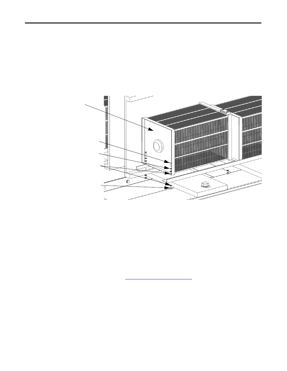
Figure 26 - Isolation Transformer Hardware Location
5.
Install the new fan in reverse order of removal.
If necessary, install new tie straps around the a, b, c, and o cables through
the fan vent.
Inspect Isolation Transformer
1.
Verify the fan is rotating in the proper direction.
2.
Verify the incoming and outgoing power cable connections are torqued to
specifications.
Torque Requirements on page 129
.
3.
Check the cabinet interior and Isolation Transformer windings and
remove any foreign material. Vacuum dust or debris from the Isolation
Transformer cabinet.
4.
Check for any physical evidence of damage or degradation of components.
M6 Bolt
Lock Washer
Washer
M6 Nut
Isolation Transformer
Auxiliary Cooling Fan