Rockwell Automation 6012DB PowerFlex Medium Voltage Variable Frequency Drive User Manual
Page 96
96
Rockwell Automation Publication 6000-UM001B-EN-P - October 2014
Chapter 5
Preventative Maintenance and Component Replacement
5.
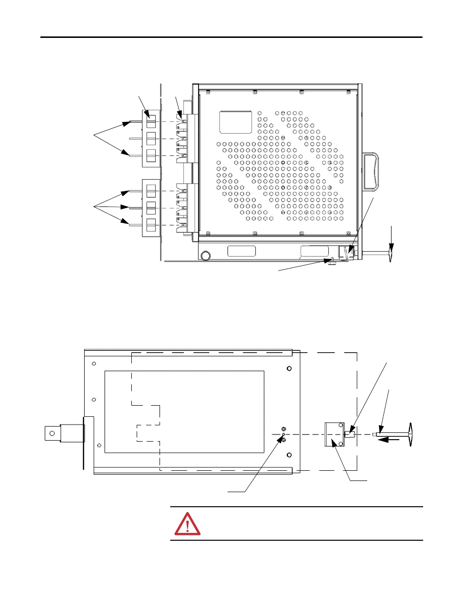
Insert the locking key into the cam mechanism actuator and rotate
clockwise while gently pushing on the face of the Power Module.
The cam mechanism will catch the pin on the tray assembly.
6.
Continue rotating the locking key until the Power Module is fully seated.
This ensures the finger assemblies at the back of the Power Module are
fully connected to the stab assemblies at the back of the Power Module
compartment.
Locking Key
Pin
Cam Mechanism
Cabinet
Stab
Assemblies
Finger
Assemblies
SIDE VIEW
Connection to
Motor Phase Bus
Three Phase
Input Power
from Isolation
Transformer
Pin
Cam Mechanism
TOP VIEW
Locking Key
Cam Mechanism Actuator
ATTENTION: The Power Module finger assemblies must be fully seated on the
cabinet stab assemblies.