Rockwell Automation 2706-M1 MESSAGEVIEW 421 HARDWARE MANUAL User Manual
Page 110
7–2
Troubleshooting and Maintenance
Publication 2706–816
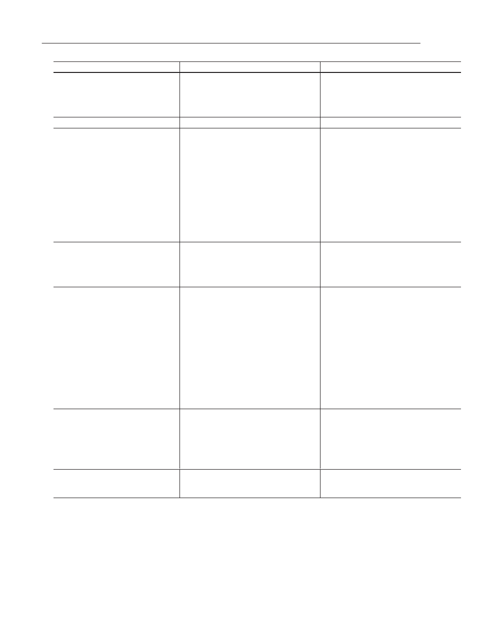
Problem
Probable Cause(s)
Corrective Action(s)
The terminal does not power up.
1. Improper connection to power source.
2. Internal fuse blown.
1. Verify correct voltage and polarity at power ter-
minals on the back of the terminal.
2. Check condition of internal fuse. Determine rea-
son for fuse blowing. Contact Allen-Bradley for
fuse replacement.
The terminal powers up with a self-test error.
1. Terminal senses an internal problem.
1. Refer to Appendix B for self-test error codes.
The terminal does not communicate with the
controller.
1. Communications (COMM) fault.
2. Cabling problem.
3. Baud rates not set properly.
4. Controller not in run mode.
5. Terminal node and maximum node numbers
are not set properly.
6. Controller fault.
7. Terminal is in simulate mode.
1. Check status of COMM LED, refer to section
“Terminal Status Indicators”.
2. Verify cable condition and connections using
cable diagrams in Chapter 6.
3. Verify that terminal and controller are set at the
same Baud rate.
4. Place controller in run mode.
5. Verify node number settings.
6. Refer to user manual for controller.
7. Disable simulate mode in the terminal from the
Front Panel Editor.
The terminal does not communicate with a
computer that has MessageBuilder installed.
1. Cabling problem.
2. RS-232 Port is configured to communicate with
an auxiliary device (see Page 3–3).
1
Verify cable condition and connections using
cable diagrams in Chapter 6.
2. Switch RS-232 port to communicate with
MessageBuilder instead of an auxiliary device
(see Page 3–3).
Terminal does not communicate with an ASCII
Trigger device or an auxiliary device.
1. Communications (COMM) fault.
2. Cabling problem.
3. Baud rates not set properly.
4. Terminal node and maximum node numbers
are not set properly.
5. Computer fault.
6. INTERCHANGE driver not properly loaded.
7. RS-232 Port is configured to communicate with
MessageBuilder (see Page 3–3).
1. Check status of COMM LED, refer to
section “LED Indicators”.
2. Verify cable condition and connections using
cable diagrams in Chapter 6.
3. Verify that terminal is set at 19200 Baud.
4. Verify node number settings.
5. Refer to computer user manual.
6. Refer to the MessageBuilder Software User
Manual (Publication 2706-817).
7. Switch RS-232 port to communicate with the
ASCII Trigger device or the auxiliary device
(see Page 3–3).
Variable data does not update or display.
1. Data is not present at display data tag address.
2. Communications problem.
1. Check logic controller program. Verify that data
is present. Refer to user manual for controller.
2. Check status of Comm LED, refer to “Terminal
Status Indicators” section. Refer to problem
‘The terminal does not communicate with the
controller’ for additional troubleshooting instruc-
tions.
Variable data does not update in display but
appears as asterisks ****.
1. Terminal is not communicating with controller.
2. The value is invalid or exceeds the field width
defined for the variable.
1. Download application and try again.
2. Change the field width defined for variable.