Rockwell Automation 6189V-xxxx Non-display Industrial Computers User Manual User Manual
Page 25
Rockwell Automation Publication 6177R-UM002D-EN-P - October 2014
25
Installation
Chapter 2
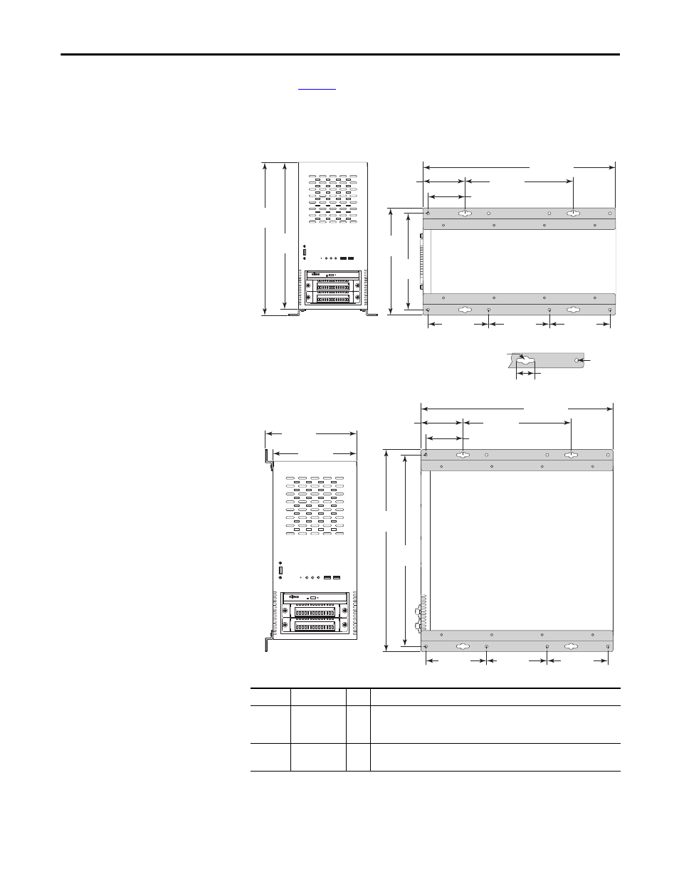
to decide which mounting holes to use on the bracket.
5. Drill holes in the wall or shelf to accommodate screws sized M6…M8.
Figure 9 - Mounting Hole Locations on 750R Computers
6. Fasten the computer to the wall or shelf with M6…M8 mounting screws.
Callout
Dim, mm (in.) Qty
Description
A
Ø 10 (0.39)
4
Use these mounting holes for the following.
• You are replacing a legacy computer.
• Shock and vibration are not environmental elements.
B
Ø 6.5 (0.25)
8
Use these mounting holes when shock and vibration are environmental
elements.
Bottom Mounting Bracket Hole Locations
Dimensions are in mm (in.).
IMPORTANT: Bottom view is enlarged
for detail and not in scale to front view.
120 (4.73)
120 (4.73)
120 (4.73)
24 (0.95) x 4
382.1 (15.04)
60 (2.36)
240 (9.45)
210
(8.27)
194
(7.64)
70.5 (2.78)
375
(14.76)
360
(14.17)
A
B
Side Mounting Bracket Hole Locations
120 (4.73)
120 (4.73)
120 (4.73)
382.1 (15.04)
60 (2.36)
240 (9.45)
401.6
(15.81)
385.6
(15.18)
70.5 (2.78)
185 (7.28)
175 (6.89)
Mounting Hole Details (all brackets)