Rockwell Automation 5370-CUPK Color CVIM USER-PAK Option User Manual
Page 69
Chapter 7
Creating Custom Runtime Displays
7 – 10
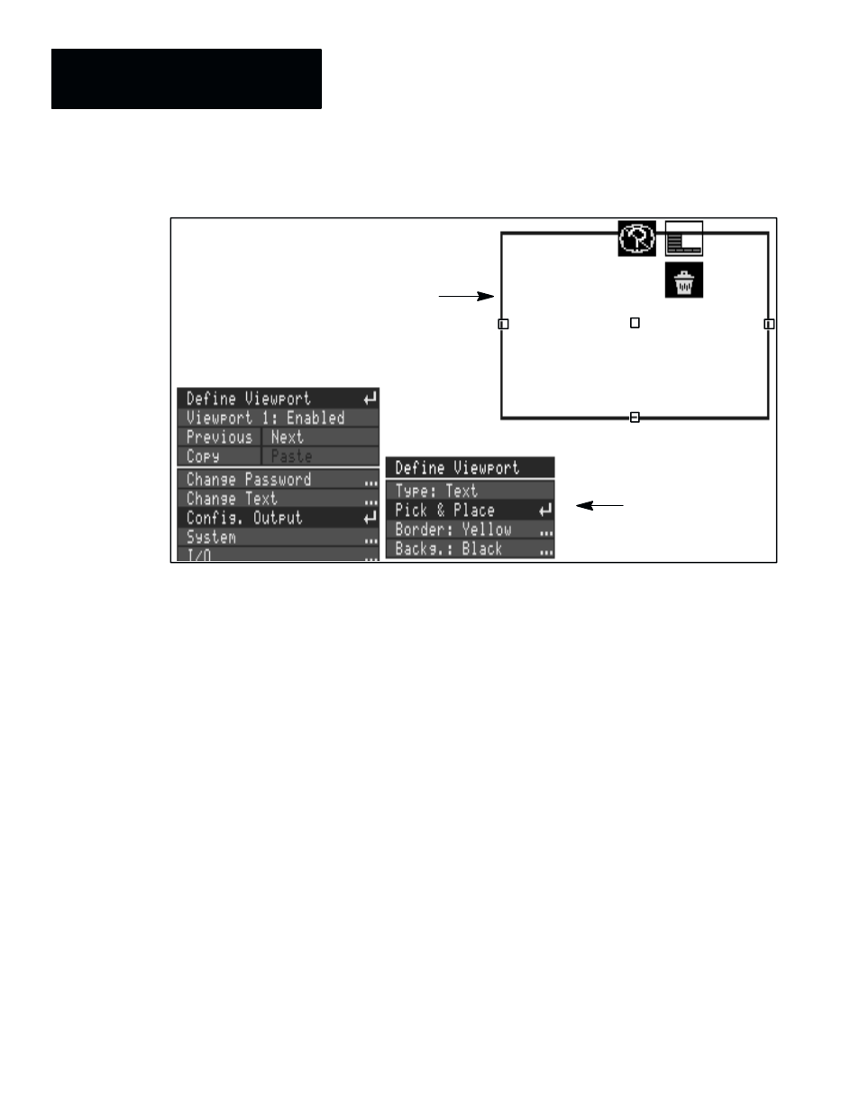
Figure 7.7 Example of placing the viewport
Pick & Place box
Viewport placed in
upper right corner
during setup.
Here are additional considerations when selecting and positioning viewports:
Position Limitation: The bottom portion of the screen (about 15% or so) is
reserved for the runtime menus, and you will not be able to drag a
Text
or
Graph
viewport border into this region. However,
Tool
viewports
encompass the entire screen, and
Tool
viewport strings can be placed
anywhere on the screen, including the runtime menu area.
Multiple Viewports Displayed on the Same Screen: You can display more
than one viewport on the same runtime display page (see “Selecting Display
Pages and Page Numbers” in this chapter). In doing so, you would need to
strategically select the viewport number of each (see below), as well as set
the size and position of each viewport according to display requirements.
Viewport Numbering and Layering: Viewports are displayed in numerical
order. Thus, if one viewport is placed partially or completely within another,
the viewport with the higher number will be displayed on “top.”
Selecting Border and Background Colors
You further define appearance of the viewport (for either a
Graph
or
Text
type) by selecting the border color, and the background color. You do this
using the
Border
and
Backg.
menu items, respectively.
Note: The
Border
and
Backg.
items are disabled for
Tool
viewports.