2 - ultra3000 connector data, Chapter objectives, Understanding ultra3000 connectors – Rockwell Automation 2090 Ultra3000 Installation Manual User Manual
Page 43: Ultra3000 connector data, Chapter
1
Publication 2098-IN003E-EN-P — April 2004
Chapter
2
Ultra3000 Connector Data
Chapter Objectives
This chapter provides I/O, encoder, and serial interface connector
locations and signal descriptions for your Ultra3000. This chapter
includes:
• Understanding Ultra3000 Connectors
• Understanding Ultra3000 I/O Specifications
• Understanding Motor Encoder Feedback Specifications
• Understanding Auxiliary Encoder Feedback Specifications
• Understanding the Serial Interface
Switch and LED locations are shown, however for switch and LED
configuration, refer to the Ultra3000 Digital Servo Drives Integration
Manual (publication 2098-IN005x-EN-P).
Understanding Ultra3000
Connectors
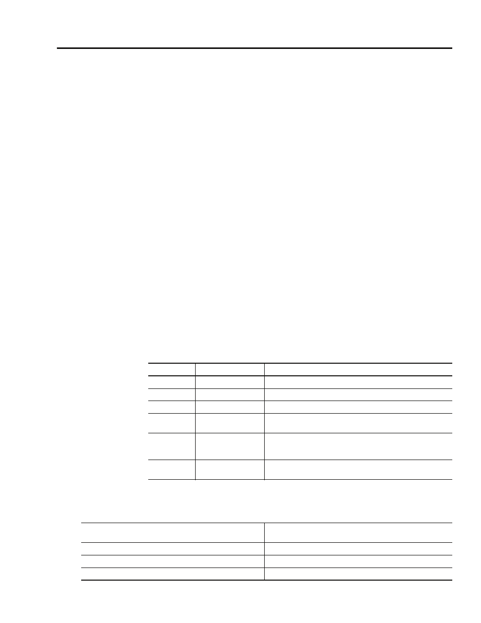
The following table provides a brief description of the Ultra3000 front
panel connectors and describes the connector type.
All signal connections on the Ultra3000 use commonly available
D-shell type connectors.
Designator
Description
Connector
CN1
User Input/Output
44-pin high-density D-shell
CN2
Motor Feedback
15-pin high-density D-shell
CN3
Serial Port
9-pin standard D-shell
TB
DC bus, Motor and
AC power
9-position screw style barrier terminal strip
(2098-DSD-005x-xx, -010x-xx, and -020x-xx)
TB1
DC bus, Motor, AC
power, and auxiliary
AC power
11- or 12-position screw style barrier terminal strip
(2098-DSD-030x-xx, -075x-xx, -150x-xx, HVxxx-xx, and HVxxxX-xx)
TB2
Shunt
3-position screw style barrier terminal strip
(2098-DSD-030x-xx, -075x-xx, -150x-xx, HVxxx-xx, and HVxxxX-xx)
For connector pin-outs and the location of connectors,
switches, and status LEDs on:
Refer to:
2098-DSD-xxx and -HVxxx Ultra3000 drives
Figures 2.1-2.4 and the tables that follow on pages 2-2 through 2-9.
2098-DSD-xxx and -HVxxx Ultra3000 drives with SERCOS interface
Figures 2.5-2.8 and the tables that follow on pages 2-10 through 2-17.
2098-DSD-xxx and -HVxxx Ultra3000 drives with DeviceNet interface
Figures 2.9-2.12 and the tables that follow on pages 2-18 through 2-25.