Rockwell Automation 2090 Ultra3000 Installation Manual User Manual
Page 106
Publication 2098-IN003E-EN-P — April 2004
3-10
Connecting Your Ultra3000
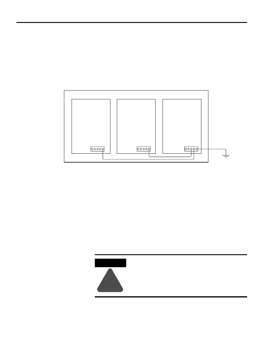
Grounding Multiple Subpanels
To ground multiple subpanels, refer to the figure below.
Note: HF bonding is not illustrated. For HF bonding information, refer
to Bonding Multiple Subpanels on page 1-12.
Figure 3.10
Subpanels Connected to a Single Ground Point
Motor Power Cable Shield Termination
Factory supplied motor power cables for MP-Series, 1326AB, and F-,
H-, N-, and Y-Series motors are shielded, and the power cable is
designed to be terminated at the drive during installation. A small
portion of the cable jacket is removed which exposes the shield braid.
The exposed area must be clamped to the bottom of the drive chassis
(refer to Figure 3.11) or the front of the drive chassis (refer to Figure
3.12) using the clamp provided.
Always follow NEC and
applicable local codes
Ground grid or power
distribution ground
ATTENTION
!
To avoid hazard of electrical shock, ensure shielded
power cables are grounded at a minimum of one
point for safety.