Page b-2, Page b-4 – Rockwell Automation 2090 Ultra3000 Installation Manual User Manual
Page 10
Publication 2098-DU003B-EN-P — September 2006
6
Ultra3000 Digital Servo Drive Installation Manual
Page B-2
Replace notes 6 and 7 in the Ultra3000 Interconnect Diagram Notes
with the ones shown below. The new versions include information
regarding the placement of ac line filters and routing of wires.
Page B-4
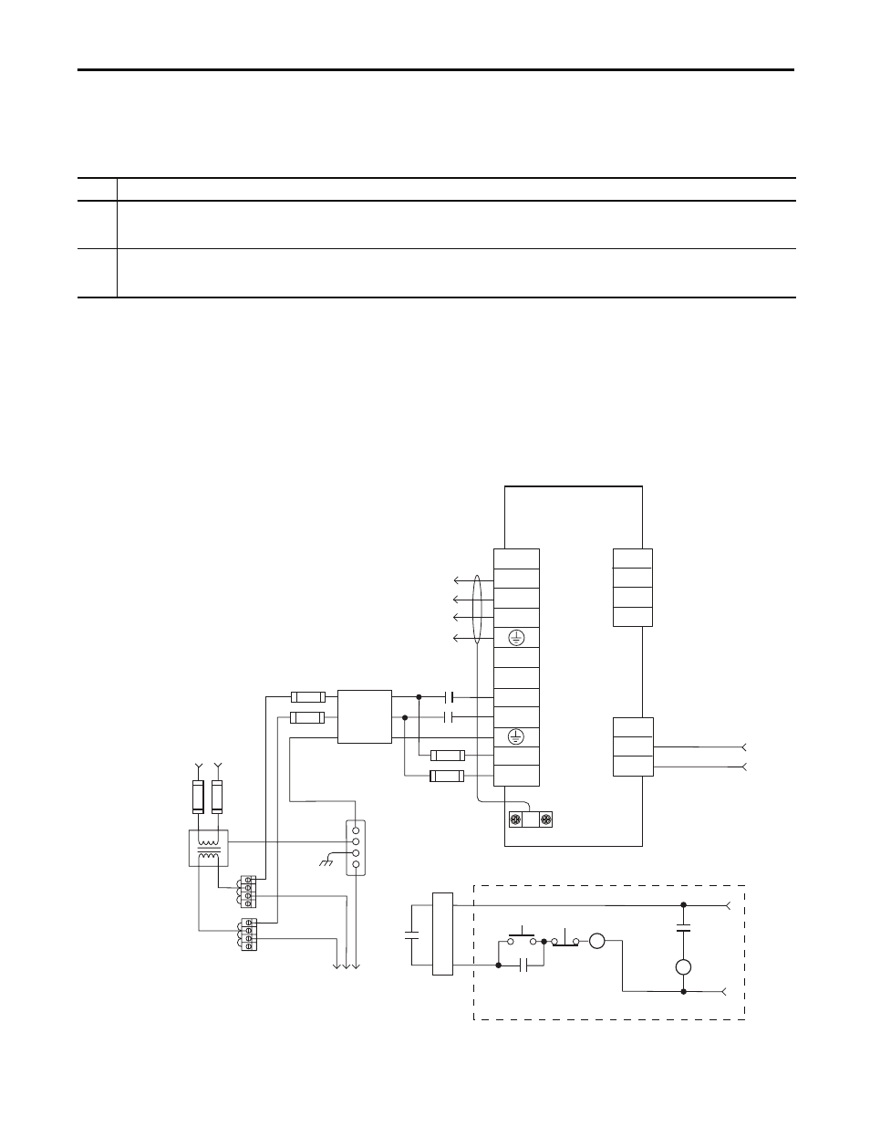
Replace the interconnect diagram on page B-4 with the one shown
below. The new diagram changes the recommended wiring of input
fusing, ac line filter, and contactor.
Figure B.2
Typical Power Wiring of Ultra3000 System
(2098-DSD-030x-xx)
Note:
Information:
6
May be used to maintain power to logic section of drive and status LED indicators when main ac input power is removed. A separate ac line
source may be used if voltage is between 88-265V ac (rms) on 2098-DSD-xxx (230V drives) or 207-528V ac (rms) on 2098-DSD-HVxxx (460V
drives). In this configuration, a separate line filter for logic power may be required.
7
Place the ac (EMC) line filter as close to the drive as possible and do not route very dirty wires in wireway (refer to Establishing Noise Zones, on
page 1-13). If routing in wireway is unavoidable, use shielded cable with shields grounded to the drive chassis and filter case. For ac line filter
specifications, refer to AC Line Filter Specifications in Appendix A.
TB1
U
V
W
DC+
DC-
L1
L2/N
L1 AUX
L2/N AUX
L2/N
L1
CN1
43
44
TB2
1
2
3
43
44
CN1
43
44
Ultra3000
Digital Servo Drive
2098-DSD-030x-xx
Note 13
AC Input Power
Connections
Motor Power
Connections
Single-phase
AC Line Filter
Note 7
Input Fusing *
Note 4, 5
Single-phase Input
100-240V ac (rms)
Fused Disconnect
or Circuit Breaker *
Note 1
Isolation
Transformer *
Note 2
Chassis
Bonded Cabinet
Ground Bus *
Terminal
Blocks *
Note 3
To additional
Ultra3000 drive.
Three-phase
Motor Power
Connections
Note 12
Cable Shield
Clamp
Note 9
* Indicates User Supplied Component
STOP *
START *
CR1 *
CR1 *
CR1 *
M1 *
Refer to Attention statement (Notes 10, 11)
N.O. Relay Output+
N.O. Relay Output-
Note 20
24V dc
Note 6
M1 *
Note 8
External Passive
Shunt Connections
Single-phase AC Line
50/60 Hz
Input Fusing *
Note 4, 5