Rockwell Automation 2090 Ultra3000 Installation Manual User Manual
Page 113
Publication 2098-IN003E-EN-P — April 2004
Connecting Your Ultra3000
3-17
3. Locate the TB1 terminal block and remove the plastic cover. Refer
to Understanding Ultra3000 Connectors in Chapter 2 for the front
panel connections of your Ultra3000 drive.
4. Using a screw driver, loosen the screw for each of the terminal
locations and attach wires as shown in the table below.
5. Tighten each terminal screw. Refer to the table on page 3-13 for
torque value.
6. Gently pull on each wire to make sure it does not come out of its
terminal. Re-insert and tighten any loose wires.
7. Re-attach the plastic cover to the terminal block.
IMPORTANT
The auxiliary AC power inputs require dual
element time delay (slow acting) fuses to
accommodate inrush current. Refer to the section
Ultra3000 (230V) Power Specifications in
Appendix A for the inrush current on the
auxiliary AC power input.
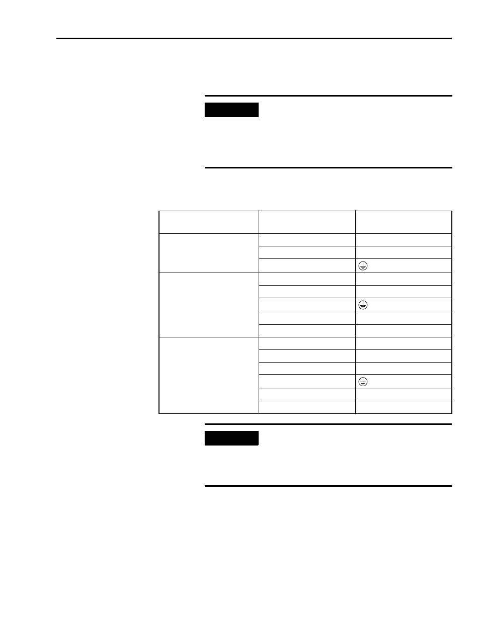
If you have this drive:
Insert this wire from
the power supply:
Into this terminal on
TB1:
2098-DSD-005x-xx,
-010x-xx, or -020x-xx
L1
L1
L2
L2/N
Ground
2098-DSD-030x-xx
L1
L1
L2
L2/N
Ground
L1 (auxiliary AC)
L1 AUX
L2 (auxiliary AC)
L2/N AUX
2098-DSD-075x-xx,
-150x-xx
or
2098-DSD-HVxxx-xx,
-HVxxxX-xx
L1
L1
L2
L2
L3
L3
Ground
L1 (auxiliary AC)
L1 AUX
L2 (auxiliary AC)
L2/N AUX
IMPORTANT
The DC bus connections should not be used for
connecting multiple drives together. Contact your
Allen-Bradley representative for further
assistance if the application may require DC
power connections.