Channel led indicator operation, Module error definition table -5, Channel led indicator operation -5 – Rockwell Automation 1790P-T4T0 CompactBlock LDX I/O Thermocouple Modules User Manual
Page 55: Module error definition table
Publication 1790-UM003A-EN-P
Diagnostics and Troubleshooting 4-5
Module Error Definition Table
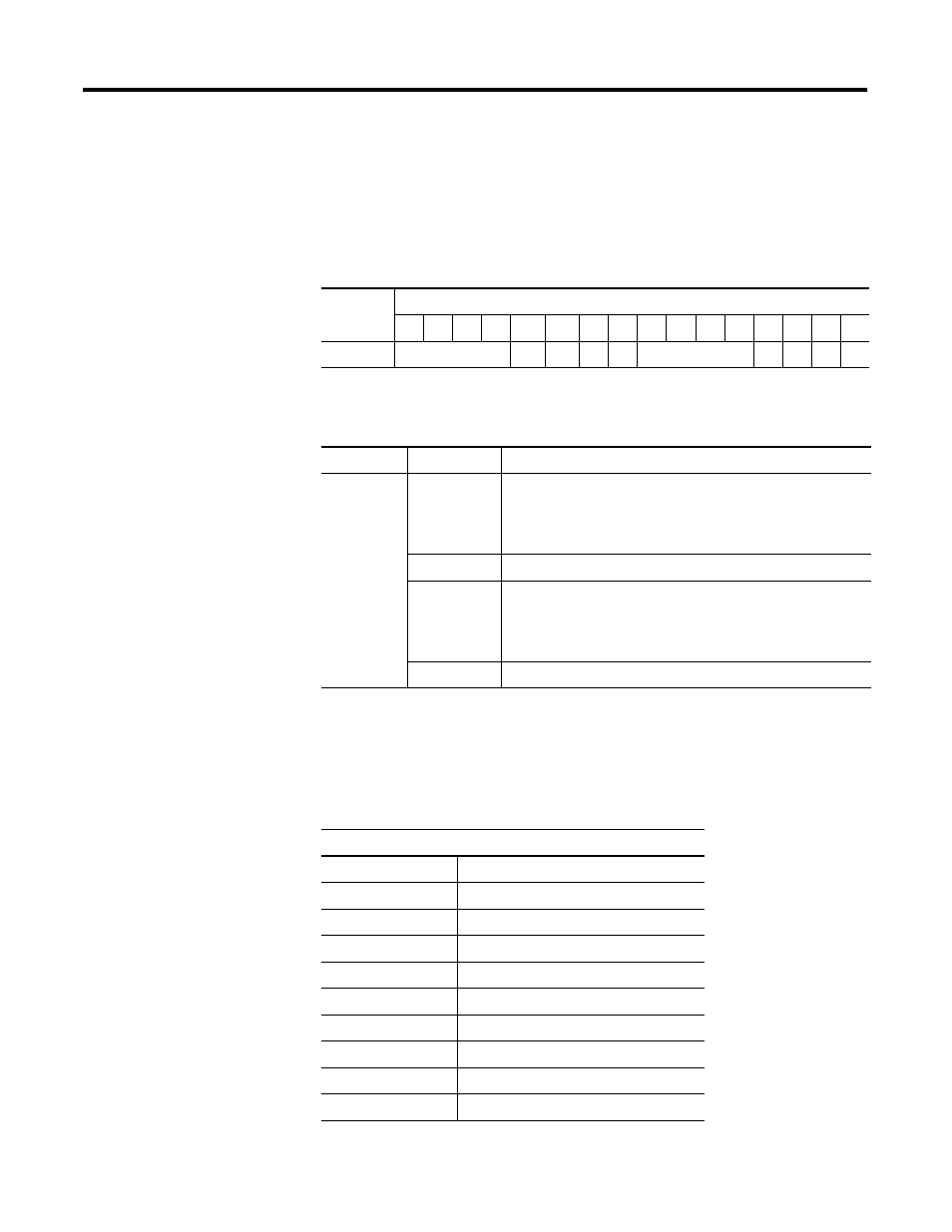
Thermocouple/mV module errors are expressed on a channel basis in
input read word 4. The structure of the status data is shown in the
following table.
Channel LED Indicator
Operation
Individual channel LED indicator operation is shown in the following
table.
Table 4.4 Word Bit Position
Word
Bit Description
15
14
13
12
11
10
9
8
7
6
5
4
3
2
1
0
4
Not Used
S11 S10 S9 S8
Not Used
S3 S2 S1 S0
Table 4.5 Bit Descriptions
Word
Decimal Bit
Description
Read Word 4
Bits 00-03
Underrange for individual channels. Bit 00 corresponds to input
channel 0, bit 01 corresponds to input channel 1 and so on.
When set (1), the input signal if below the input channel’s
minimum range
Bits 04-07
Not used: Set to 0
Bit 08-11
Overrange for individual channels. Bit 08 corresponds to input
channel 0, bit 09 corresponds to input channel 1 and so on.
When set (1), the input signal if above the input channel’s
maximum range, or open thermocouple is detected
Bit 12-15
Not used: Set to 0
Table 4.6 Individual Channel LEDs Indicator
I/O Channel LED Status Indicator
Status:
Description
Flashing Green/Red
Power up
Off
Off line
Red
On line and no field power
Red
DeviceNet connection and no field power
Flashing Red
Field power and open wire
Green
Field power and valid input
Flashing Red
Input over range, open input
Flashing Red
Input under range
Flashing Red
Recoverable fault