Input data file, Input data file -2, Input data values – Rockwell Automation 1790P-T4T0 CompactBlock LDX I/O Thermocouple Modules User Manual
Page 32: Under-range flag bits (s0 to s3)
Publication 1790-UM003A-EN-P
3-2 Module Data, Status, and Channel Configuration for DeviceNet
Input Data File
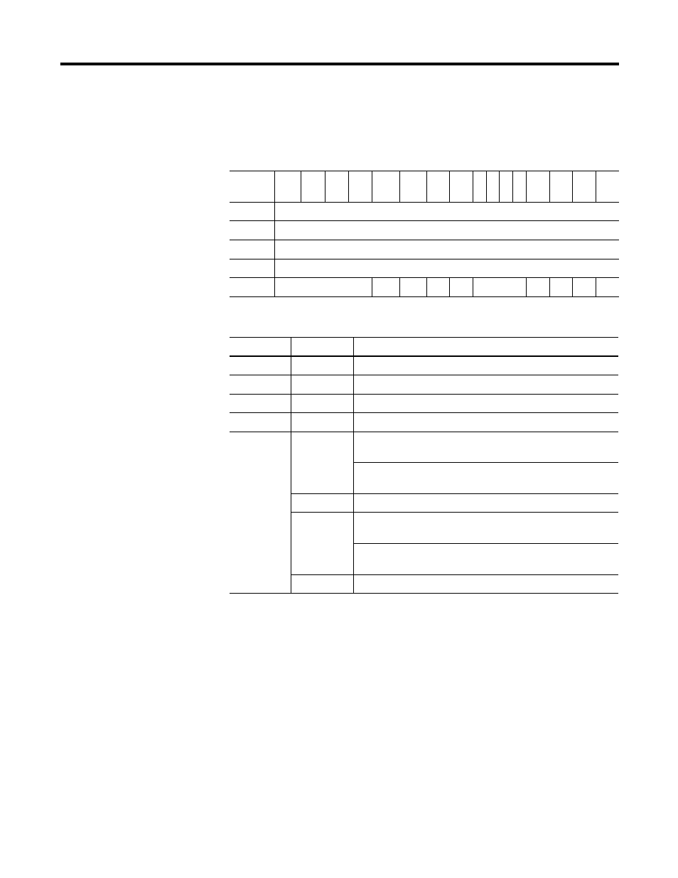
The input data table lets you access thermocouple/mV input module read
data for use in the control program, via word and bit access. The data
table structure is shown in the tables below.
Input Data Values
Data words 0 through 3 correspond to channels 0 through 3 and contain
the converted analog input data from the input device.
Under-Range Flag Bits (S0 to S3)
Under-range bits for channels 0 through 3 are contained in word 4, bits
0-3. When set (1), the under-range flag bit indicates a thermocouple
temperature that is less than the minimum allowed temperature. The
module automatically resets (0) the bit when the data value is again
within the normal operating range.
Table 3.1 Input Data Table
Word/
Bit
15
14
13
12
11
10
9
8
7 6 5 4
3
2
1
0
0
Thermocouple Input Data Channel 0
1
Thermocouple Input Data Channel 1
2
Thermocouple Input Data Channel 2
3
Thermocouple Input Data Channel 3
4
Not Used
S11
S10
S9
S8
Not Used
S3
S2
S1
S0
Table 3.2 Input Data Table
Word
Decimal Bit Description
Read Word 0 Bits 00-15
Channel 0 input data
Read Word 1 Bits 00-15
Channel 1 input data
Read Word 2 Bits 00-15
Channel 2 input data
Read Word 3 Bits 00-15
Channel 3 input data
Read Word 4 Bits 00-03
Underrange for individual channels - Bit 00 corresponds to input
channel 0, bit 01 corresponds to input channel 1 and so on.
When set (1), the input signal is below the input channel’s
minimum range.
Bits 04-07
Not used: Set to 0
Bits 08-11
Overrange for individual channels - Bit 08 corresponds to input
channel 0, bit 09 corresponds to input channel 1 and so on.
When set (1), the input signal is above the input channel’s
maximum range, or open thermocouple is detected.
Bit 12-15
Not used: Set to 0.