Wiring the module -14 – Rockwell Automation 1790P-T4T0 CompactBlock LDX I/O Thermocouple Modules User Manual
Page 28
Publication 1790-UM003A-EN-P - May 2002
2-14 Installation and Wiring
Wiring the Module
After the module is properly installed, follow the wiring procedure
below, using the proper thermocouple extension cable, or Belden
8761 for non-thermocouple applications.
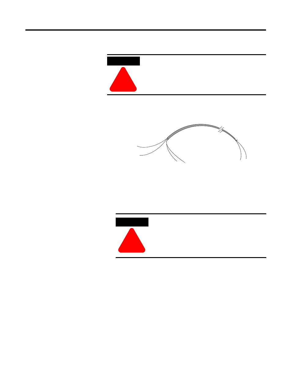
To wire your module follow these steps.
1. At each end of the cable, strip some casing to expose the
individual wires.
2. Trim the signal wires to 2-inch (5 cm) lengths. Strip about 3/16
inch (5 mm) of insulation away to expose the end of the wire.
3. At one end of the cable, twist the drain wire and foil shield
together, bend them away from the cable, and apply shrink wrap.
Then earth ground at the preferred location based on the type of
sensor you are using. See Grounding on page 2-13.
ATTENTION
!
To prevent shock hazard, care should be taken when
wiring the module to analog signal sources. Before
wiring any module, disconnect power from the
system power supply and from any other source to
the module.
ATTENTION
!
Be careful when stripping wires. Wire fragments
that fall into a module could cause damage at
power up.
cable
signal wire
signal wire
drain wire
foil shield
signal wire
signal wire
Cut foil shield
and drain wire