Channel configuration -5, Channel configuration – Rockwell Automation 1769-OF2 Compact I/O Analog Modules User Manual
Page 55
Publication 1769-UM002B-EN-P - July 2005
Module Data, Status, and Channel Configuration for the Input Modules 3-5
Channel Configuration
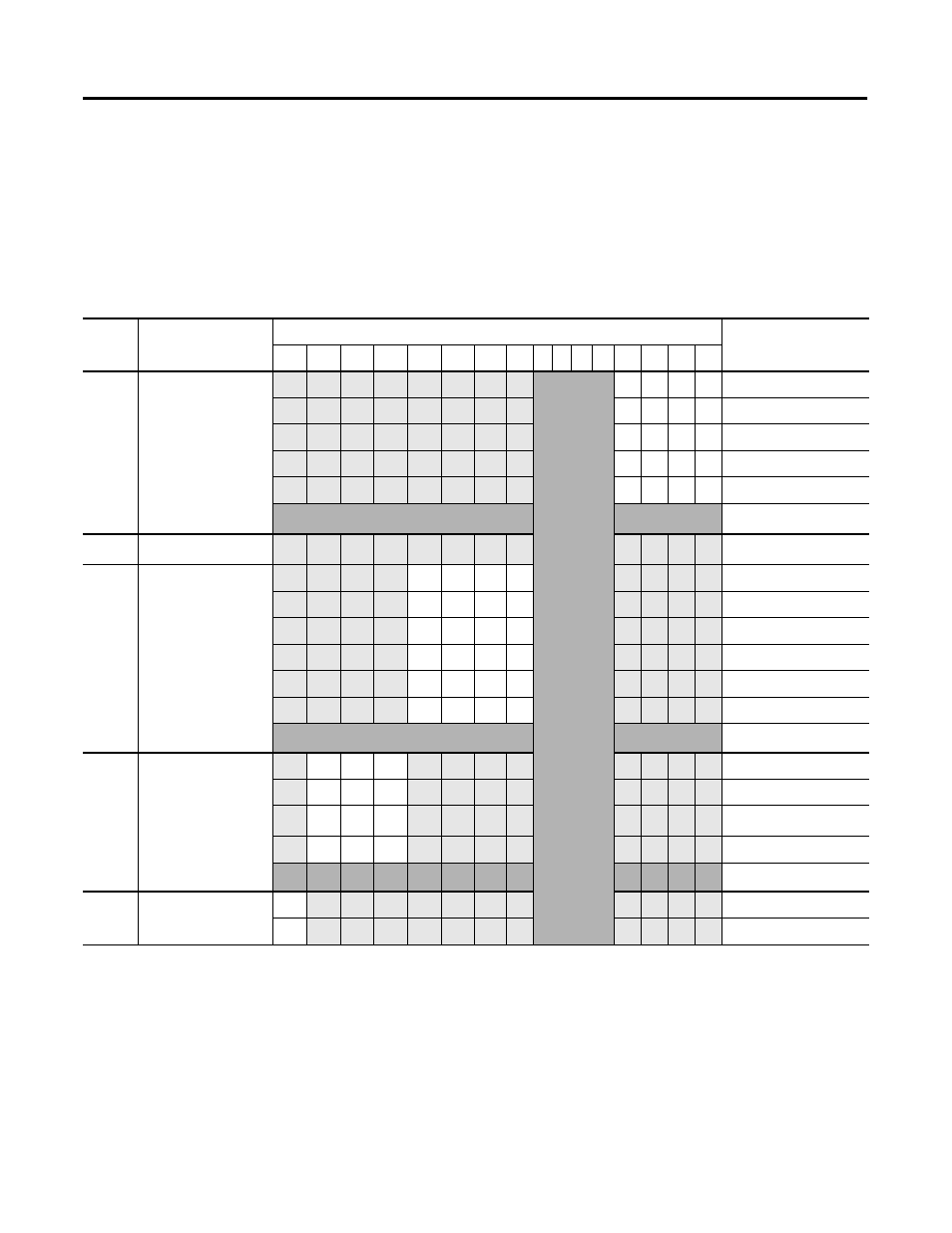
Each channel configuration word consists of bit fields, the settings of which
determine how the channel operates. See the table below and the descriptions
that follow for valid configuration settings and their meanings. The default bit
status of the configuration file is all zeros.
Table 3.3 Bit Definitions for Channel Configuration Words 0 through 3
Bit(s)
Define
These bit settings
Indicate this
15
14
13
12
11
10
9
8
7 6 5
4
3
2
1
0
0 to 3
Input Filter Select
Not Used
0
0
0
0
60 Hz
0
0
0
1
50 Hz
0
0
1
0
Not Used
0
0
1
1
250 Hz
0
1
0
0
500 Hz
Not Used
(1)
4 to 7
Reserved
Reserved
(2)
8 to
11
Input Type/Range
Select
0
0
0
0
-10 to +10V dc
0
0
0
1
0 to 5V dc
0
0
1
0
0 to 10V dc
0
0
1
1
4 to 20 mA
0
1
0
0
1 to 5V dc
0
1
0
1
0 to 20 mA
Not Used
12 to
14
Input Data
Format Select
0
0
0
Raw/Proportional Data
0
0
1
Engineering Units
0
1
0
Scaled for PID
(3)
0
1
1
Percent Range
Not Used
15
Enable Channel
1
Enabled
0
Disabled
(1)
Any attempt to write a non-valid (not used) bit configuration into any selection field results in a module configuration error. See Configuration Errors on page 5-6.
(2)
If reserved bits are not equal to zero, a configuration error occurs.
(3)
This range is applicable to the PID function of the MicroLogix 1500 packaged controller, PLC, or SLC controllers. Logix controllers can use this or one of the other ranges for
their PID functions.