Rockwell Automation 1769-OF2 Compact I/O Analog Modules User Manual
Page 37
Publication 1769-UM002B-EN-P - July 2005
Installation and Wiring 2-13
As input source impedance (Rs) and/or resistance (dc) of the cable (Rc) get
larger, system accuracy decreases. If you determine that the inaccuracy error is
significant, implementing the following equation in the control program can
compensate for the added inaccuracy error due to the impedance of the source
and cable.
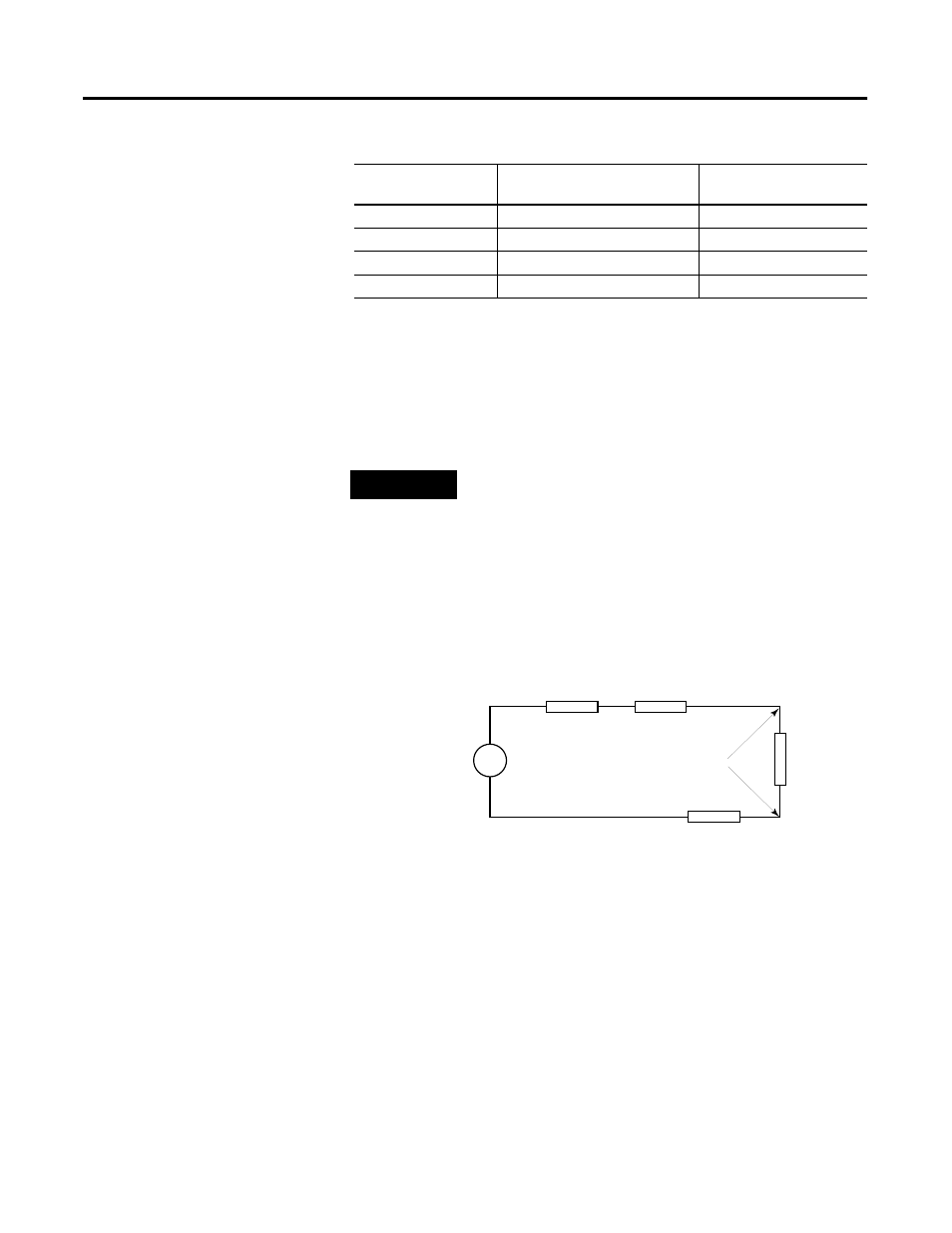
Effect of Device and Cable Output Impedance on Output Module Accuracy
The maximum value of the output impedance is shown in the example below,
because it creates the largest deviation from an ideal voltage source.
Figure 2.7 Output Module Accuracy
Where:
Rc = DC resistance of the cable (each conductor)
depending on cable length
Rs = Source impedance
(15
Ω for 1769-OF2 and 1 Ω for 1769-OF8V)
Ri = Impedance of the voltage input
(220 K
Ω for 1769-IF4)
Vs = Voltage at the output of 1769-OF2
Vin = Measured potential at the module input
%Ai = Percent added inaccuracy in a voltage-based
system due to source and cable impedance.
Table 2.2 Effect of Cable Length on Input Accuracy
Length of Cable (m)
dc resistance of the cable,
Rc (
Ω)
Accuracy impact at the
input module
50
2.625
0.00238%
100
5.25
0.00477%
200
10.50
0.00954%
300
15.75
0.0143%
TIP
In a current loop system, source and cable impedance do
not impact system accuracy.
Vs
Vin
Rs
2
Rc
×
(
) Ri
+
+
[
]
Ri
-------------------------------------------------------
×
=
V in
Vs
Ri
Rc
Rc
Rs
+
-
Vin
Ri
Vs
×
[
]
Rs
2
Rc
×
(
) Ri
+
+
[
]
-------------------------------------------------------
=