Output module block diagram – Rockwell Automation 1769-OF2 Compact I/O Analog Modules User Manual
Page 23
Publication 1769-UM002B-EN-P - July 2005
Overview 1-9
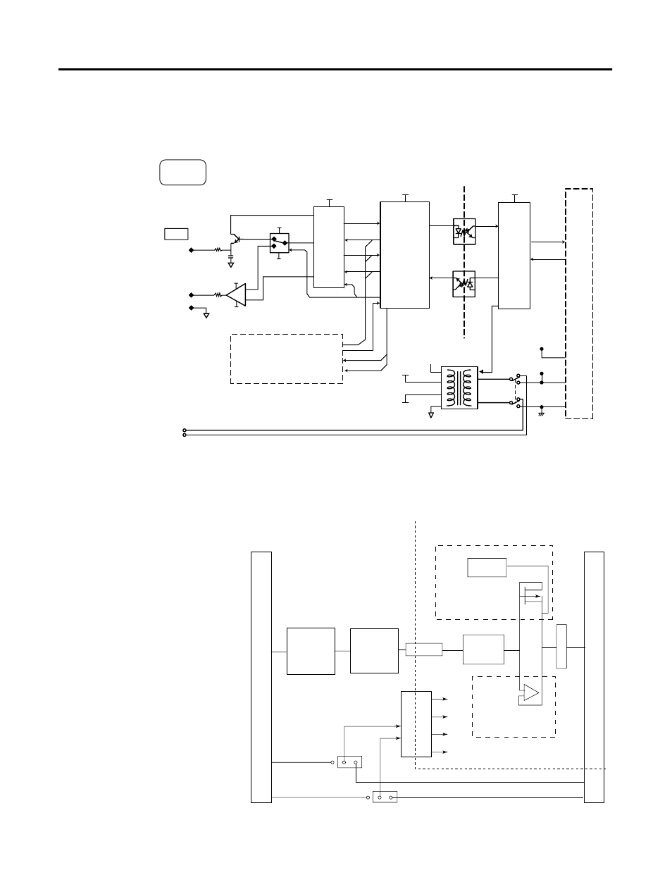
Output Module Block Diagram
The output module uses a digital-to-analog (D/A) converter to read the digital
output data from the controller and convert it to an analog output signal.
Figure 1.7 1769-OF2 Block Diagram
Figure 1.8 1769-OF8C and -OF8V Block Diagram
The following diagram shows only one of eight outputs. For each analog
output, only one of the sections shown in broken-line boxes is implemented.
The 1769-OF8C module uses only the Current Out section while the
1769-OF8V module uses only the Voltage Out section.
VA2
VA1
VA3
VS1
VS2
A-GND
S-GND
MCU
D/A
ASIC
VA1
VS1
VA2
VA2
VA3
CH1
CH0
A-GND
A-GND
Iout+
Vout+
COM
Iout
TXD
RXD
Iout
Refout
+24V dc
dc Neutral
Output
(same as above)
Analog Switch
DC/DC
Power Supply
Galvanic
Isolation
Bus
Selec
Selec
Latch
Latch
16 pin backplane connector
18 pin T
erminal Block
ASIC
CFU
64K Flash/
2K RAM
500VDC Isoleted
Power Supply
+5V
+15V
-15V
GND
OC
Detect
16 Bit
DAC
Voltage Out
+
-
ESD Limit
EXT 24VDC
GND
JP
+24 VDC
GND
OPTOS
Curent Out