Chapter 3, 1769-if4 input module addressing, 1769-if4 input module addressing -1 – Rockwell Automation 1769-OF2 Compact I/O Analog Modules User Manual
Page 51: Chapter
1
Publication 1769-UM002B-EN-P - July 2005
Chapter
3
Module Data, Status, and Channel
Configuration for the Input Modules
This chapter examines the analog input modules’ data table, channel status,
and channel configuration word. The 1769-IF4 module information follows.
For 1769-IF8 module information, see page 3-16.
1769-IF4 Input Module
Addressing
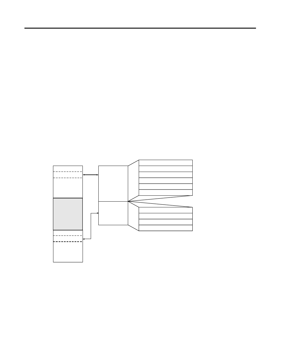
The 1769-IF4 memory map shows the input and configuration image tables
for the 1769-IF4. Detailed information on the input image table can be found
in 1769-IF4 Input Data File on page 3-2.
Figure 3.1 1769-IF4 Memory Map
Channel 0 Data Word
Word 0
Word 1
Word 2
Word 3
Word 4, bits 0 to 3
Word 5, bits 0 to 15
Channel 1 Data Word
Channel 2 Data Word
Channel 3 Data Word
General Status Bits
Over-/Under-range Bits
Channel 0 Configuration Word
Channel 1 Configuration Word
Channel 2 Configuration Word
Channel 3 Configuration Word
Word 0
Word 1
Word 2
Word 3
Input Image
6 words
Configuration
File
4 words
slot e
slot e
Input Image
Configuration
File
Output Image
File
Memory Map
Bit 15
Bit 0