External power switch, Field wiring connections, External power switch -10 – Rockwell Automation 1769-OF2 Compact I/O Analog Modules User Manual
Page 34: Field wiring connections -10, Grounding -10, Grounding
Publication 1769-UM002B-EN-P - July 2005
2-10 Installation and Wiring
External Power Switch
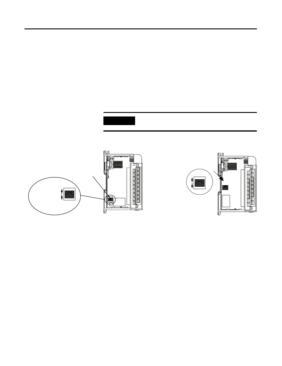
The analog modules have an external 24V dc power switch which gives you
the option of using an external power supply. The switch is located in on the
lower left portion of the module’s circuit board, as shown below. With the
switch pressed on the top (default), 24V dc power is drawn from the 1769
system power supply via the 1769 I/O bus. Pressed on the bottom, 24V dc
power is drawn from the external power supply.
Wire the external power supply to the module via the module’s terminal block.
The external power supply must be Class 2 rated, with a 24V dc range of 20.4
to 26.4V dc and a minimum current rating that meets the needs of the modules
used in your application. Refer to Maximum Current Draw on page 2-2.
Figure 2.5 External Power Switch
Field Wiring Connections
Grounding
This product is intended to be mounted to a well-grounded mounting surface
such as a metal panel. Additional grounding connections from the module’s
mounting tabs or DIN rail (if used) are not required unless the mounting
surface cannot be grounded. Refer to Industrial Automation Wiring and Grounding
Guidelines, Allen-Bradley publication 1770-4.1, for additional information.
IMPORTANT
Only 1769-IF4 and -OF2 Series B modules have the 24V
dc power switch.
BUS
EXT
Bus Power (default)
External Power
External Power
Supply Switch
External Power Switch
Pressed on the Top
Bus Power (default)
Pressed on the Bottom
External Power
1769-IF4 and -OF2 Modules
1769-OF8C and -OF8V Modules