Rockwell Automation 1732E-OB8M8SR EtherNet/IP Dual Port 8-Point SOE Input and Scheduled Output Modules UM User Manual
Page 85
Rockwell Automation Publication 1732E-UM003B-EN-E - March 2014
75
Use the Sequence of Events Input and Scheduled Output Modules Chapter 10
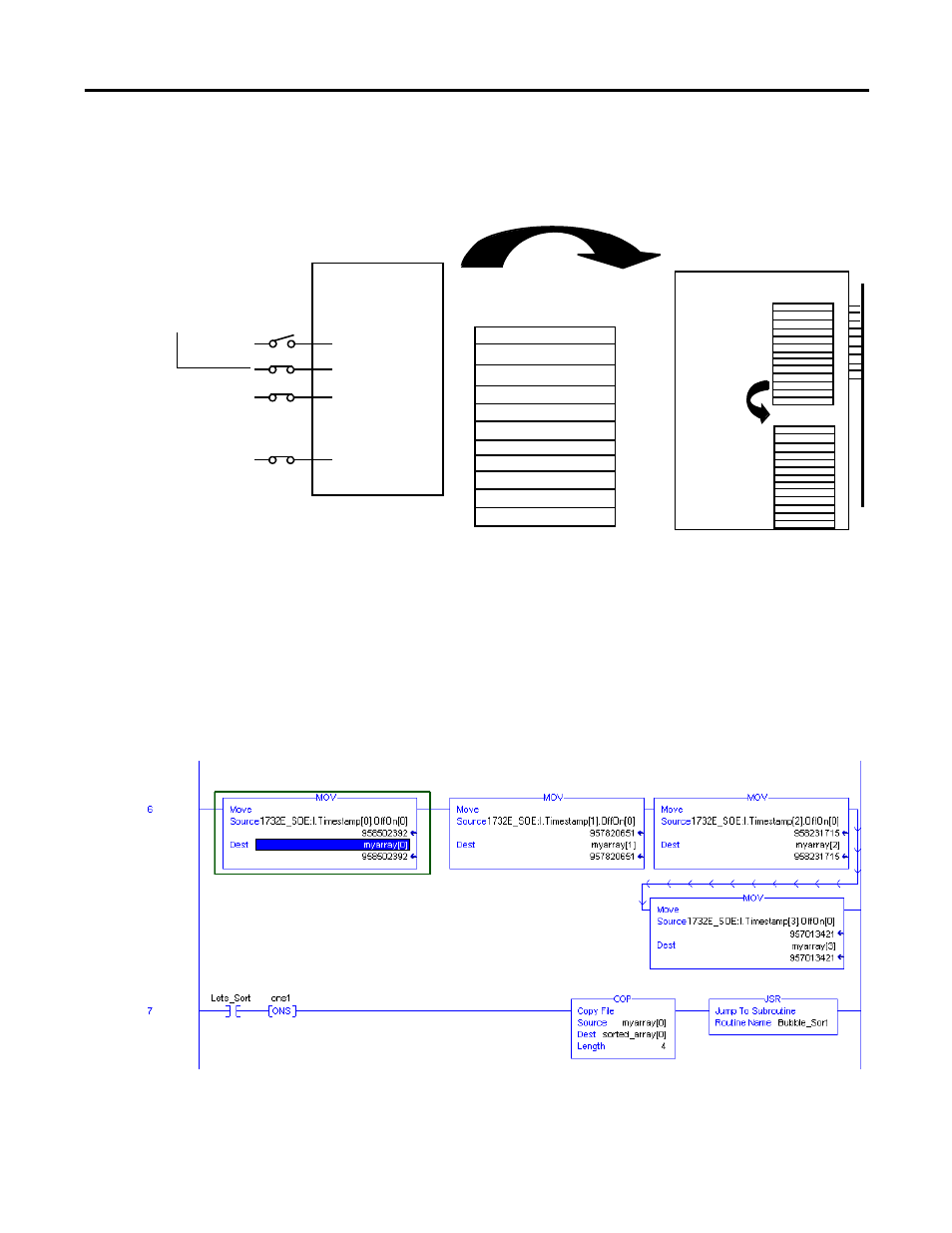
The following figure shows when to use the COP instruction. In this example,
the module timestamped a transition on input 1 and is sending input data to the
controller at each RPI. The controller copies input data from the controller tags
to a separate data structure.
Your application determines what input data should be copied from the
controller tags to a separate data structure. Although you can copy all the input
data to another array, typically, only the data from specific tags is copied.
The following figure shows an example of ladder logic in which the controller
only moves OFF to ON timestamp data for inputs 0…3 from the controller tags
to a separate data structure named myarray. The data in the myarray structure is
then moved to another array used to sort the data. In this example, 32 bits of each
64-bit timestamp are moved to the new array.
Controller tags
Separate array
4. Controller
copies
relevant
data from
controller
tags to a
separate
array.
1. Input 1 transitions
from OFF to ON.
2. Module timestamps
the transition.
3. Module sends input
data to the controller.
ControlLogix controller
I.Fault
I.EventOverlow
I.OffsetTimeStamp
I.EventNumber
I.Timestamp[16].OffOn[2]
I.Timestamp[16].OnOff[2]
I.Data
I.NewData
I.ShortCircuit
I.OpenWire
I.GrandMasterClockID
I.LocalClockOffset
I.SyncedToMaster
1732E-IB8M8SOER
I.Fault
I.OffsetTimeStamp
I.TimeStampOffOn
I.Data
I.EventOverflow
I.NewData
I.GrandMasterClockID
I.LocalClockOffset
I.TimeStampOnOff
I.EventNumber
I.SyncToMaster