Lesson 5, Pico gfx-70 pico-link project, Chapter 7 – Rockwell Automation 1760 Pico GFX-70 Controllers Quick Start User Manual
Page 43: Pico gfx-70 pico-link project -1, Chapter
1
Publication 1760-QS002A-EN-P - April 2004
Chapter
7
Lesson 5
Pico GFX-70 Pico-Link
Project
When using Pico GFX-70 devices, you can connect several basic units.
This connection is implemented using Pico's Pico-Link. This
CAN-based intraconnect allows up to 8 devices to communicate
between each other. The entire Pico-Link intraconnect can be up to
1000 meters in length.
A Pico-Link intraconnect consists of at least two basic units, with the
first one being the master and the second one being the slave. The
maximum configuration possible consists of one master and seven
slaves.
In this lesson we are going to create a Pico GFX-70 project consisting
of one master and two slaves. For this, you must be in Project View.
The first slave (intelligent slave) is to process a circuit diagram. The
second slave is only meant to operate as a remote I/O module, in
other words, without its own circuit diagram.
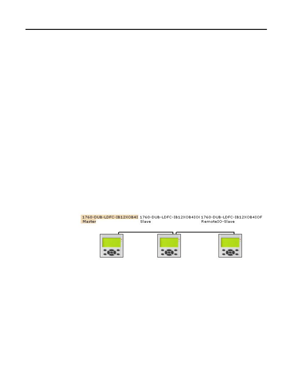
The following figure shows the required project configuration.
To create the project shown above, proceed as follows:
1. Open a new project via File, New.
2. Double-click 1760-DU series on the left in the Toolbox.
3. Then add a 1760-LDFC CPU module, a 1760-DUB display
module and a 1760-IB12XOB4IOF I/O module to the
Workbench using drag and drop. Confirm any prompts that
appear by clicking OK.
4. Repeat this configuration twice more for the other two devices
Pico-Link ID 1
Pico-Link ID 2
Pico-Link ID 3