Rockwell Automation 1760 Pico GFX-70 Controllers Quick Start User Manual
Page 11
Publication 1760-QS002A-EN-P - April 2004
Lesson 1 2-3
Toolbox [1] and can be logically linked together in the Circuit Diagram
window [3]. You can specify the properties of the operands in the
Properties field [2].
To develop a solution for our task, we first have to wire up the inputs
I1 and I2 in our circuit diagram so that they act on marker M1, which
in turn is responsible for the on/off switching of the motor. To use
input I1 in our circuit diagram, proceed as follows:
1. Left-click in the Toolbox [1] the operand called “I Input Basic
Unit” and hold down the mouse.
2. Drag the mouse, which will then change to the operand symbol
for the I input, to the right onto rectangle 1A in the circuit
diagram [3] and release the mouse button.
3. Select an operand number (in this case 1) from the I list box (on
the right of the “I”) in the Properties field [2]. As it is a local input
of this device, the 0 shown in the Station list box is unchanged.
You can also assign a comment to the operand (e.g. Motor on),
if required. Your entry is accepted immediately.
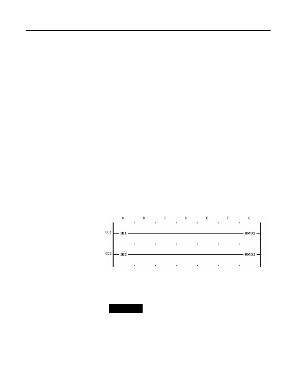
You can then add all the other operands to the circuit diagram in the
same way so that it will resemble the following figure:
To ensure a fail-safe circuit diagram, I2 has been wired as a break
contact.
TIP
You can place operands in the circuit diagram
wherever the mouse pointer takes on the
appearance of the operand symbol. When it looks
like the 'Prohibited/No Entry' sign, this indicates that
the area is reserved for a connection line.