Creating a circuit diagram, Creating a circuit diagram -2 – Rockwell Automation 1760 Pico GFX-70 Controllers Quick Start User Manual
Page 10
Publication 1760-QS002A-EN-P - April 2004
2-2 Lesson 1
2. Click the device called “1760-L12AWA”, hold down the left
mouse button, and drag the mouse (now showing a device
symbol) to the right onto the Workbench.
The Properties field [2] now shows an overview of the device
properties. Right-click the device and choose Device Information in
the context menu. The properties of the device include, for example,
the number of inputs and outputs, the number of markers, timing
relays, and counters. Use this field to verify that you have chosen the
right device before creating the circuit diagram for your application.
If necessary, delete an unsuitable device using Delete Device in the
context menu.
Creating a Circuit Diagram
Once we have selected a device in the Project View, we can now
switch to Circuit Diagram View. To do this we double-click the
device.
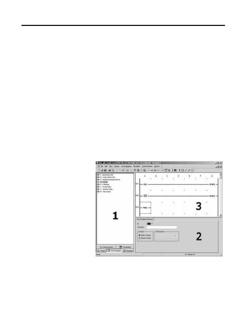
Like the Project View, the Circuit Diagram View is also divided into
three sections:
This view also consists of the Toolbox [1], the Properties field [2]
and the Workbench [3], which is also called the Circuit Diagram
window in this case.
To wire up the circuit diagram, we need operands (e.g. I inputs, Q
outputs, M markers, etc.). The operands available are displayed in the