Powermonitor meter configuration – Rockwell Automation 1413-ME-PEA Capacitor Bank Controller - Series B User Manual
Page 25
Publication 1413-UM001C-EN-P - May 2006
Installation 23
Powermonitor meter communications settings are changed using the
Powermonitor display module.
Please refer to Powermonitor Meter Configuration Parameters table.
Powermonitor Meter
Configuration
The table below lists the configuration parameters that must be set up
for correct operation of the capacitor bank controller.
For additional information regarding Powermonitor meter
configuration, please refer to the Powermonitor 3000 User Manual,
publication 1404-UM001.
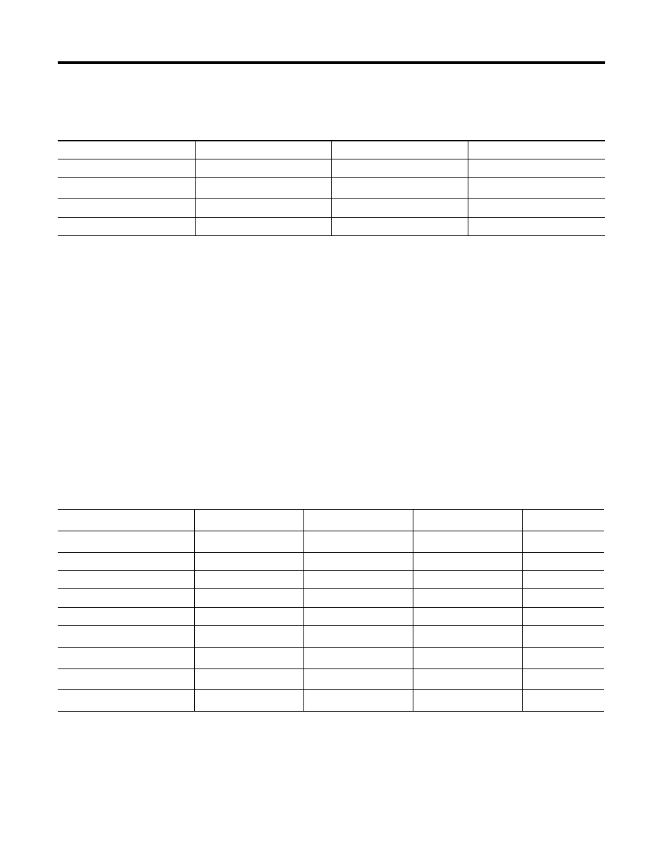
Powermonitor Ethernet Communication Settings
Device / Parameter
Powermonitor Meter 2
Powermonitor Meter 3
Powermonitor Meter 4
Node Address
102
103
104
IP Address
(1)
192.168.0.UnitID
192.168.0.UnitID
192.168.0.UnitID
Subnet Mask
255.255.255.0
255.255.255.0
255.255.255.0
Default Gateway
192.168.0.1
192.168.0.1
192.168.0.1
(1)
The Unit ID is listed on the Powermonitor nameplate.
Powermonitor Meter Configuration Parameters
Parameter
PM 1
PM 2
(4)
PM 3
(4)
PM 4
(4)
Wiring mode
(1)
PT (VT) primary voltage
PT (VT) secondary voltage
CT primary current
I4 primary current
RS-485 node number
101
(3)
102
103
104
IP address
(2)
192.168.0.101
Subnet mask
(2)
255.255.255.0
Default gateway address
(2)
192.168.0.1
(1)
Wiring mode must be Wye when using NEU or Retro CTPT mode.
(2)
Applies only to Ethernet Powermonitor meter options.
(3)
Default factory setting for base unit.
(4)
Optional additional Powermonitor meters.