Rockwell Automation 1413-ME-PEA Capacitor Bank Controller - Series B User Manual
Page 21
Publication 1413-UM001C-EN-P - May 2006
Installation 19
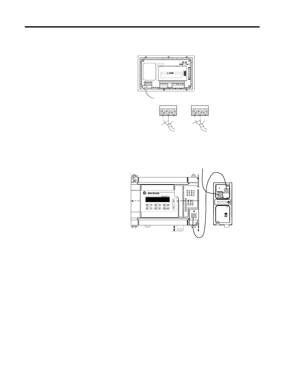
3. Connect 120V ac control power and earth ground.
4. Install the Ethernet interface module (9) within 45 cm (18 in.) of
the Channel 0 connector on the MicroLogix 1500 controller (1).
5. Verify that the DC Source switch on the Ethernet interface
module is in the Cable position.
6. Connect the cable (11) between Channel 0 of the MicroLogix
1500 controller and the Ethernet interface module.
7. Connect the PanelView 550 terminal to the Ethernet interface
module using the Ethernet crossover cable (12) if the system will
not be connected to a local area network.
8. Connect both the PanelView 550 terminal and the Ethernet
interface module to the Ethernet local area network via a
suitable hub or switch using user-provided CAT5 Ethernet cables
if the system will be connected to a local area network.
L1
L2
White
(Neutral)
Green
(Earth Ground)
L1
L2
Black (Line)
Brown (Line)
Green
(Earth Ground)
Green/Yellow
(Protective Earth)
Blue
(Neutral)
120/240V ac, 3 Wire,
U.S. Color Code
120/240V ac,
3 Wire, European
Harmonized Color Code
Power Terminal Block (fixed)
To Power Source
To Power Source
GND
GND
ETHERNET
FAULT
RS232
NET
TX/RX
TX/RX
PWR
CABLE
EXTERNAL
IP
To Ethernet LAN